65
English
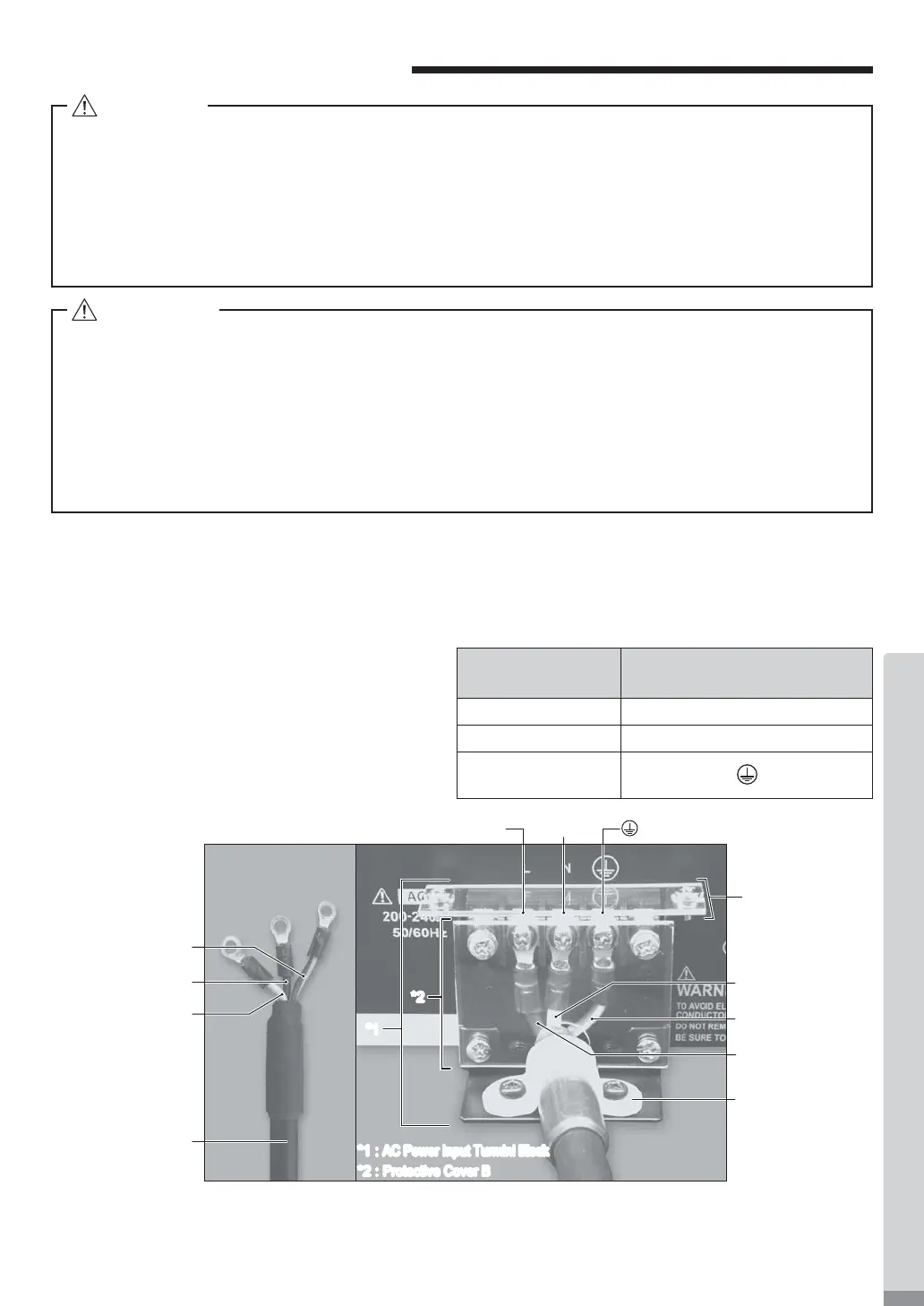
11. POWER CORD CONNECTION
(1) Loosen the mounting screws located on Protective Covers A , B and the Securing Band. Remove Protective
Covers A , B and the Securing Band from the rear of the CONTROLLER.
(2) The round terminal lugs are attached to the one side of the Power Cord. Remove the Terminal Screw from the
AC Power Input Terminal Block. Make sure to connect the round terminal to the AC Power Input Terminal Block
securely.
(Table 2, Fig. 15)
Securing Band
Protective
Cover A
Yellow / Green
Cord (For Ground)
Black Cord
Black Cord
White Cord
Green/Yellow
Cord (For Ground)
L position N position psition
White Cord
Power Cord
*2
*1
*2 :
Protective Cover B
*1 :
AC Power Input Turminl Block
Cord Collar
AC Power Input Terminal Block
connection position
Black L
White N
Green / Yellow
(For Ground)
Table. 2
Fig.15
・NAKANISHI warns all end-users not to remove the CONTROLLER's Protective Covers A and B
while the Control Power is ON, or there is power to the main power cord. Disconnect the main
power from its power source before removing the Protective Covers A and B. Not following these
instructions may lead to serious injury or death due to electric shock.
・After connecting the Power Cord, be sure to attach the Protective Covers A and B safety, dust
proo¿ ng and electric shock prevention. If the Protective Cover A and B are not attached to the
CONTROLLER, it may lead to the risk of death or serious injury by electric shock.
DANGER
・Only use grounded power sources. Using a non-speci¿ ed Power Cord, the risk of ¿ re by over-
heating of the cord is possible.
・Mis-wiring will cause damage to the CONTROLLER.
・Be sure to connect the ground wire to the earth ground. Insuf¿ cient grounding could cause an
electric shock or malfunction.
・Tighten the Terminal Screw of the AC Power Input Terminal Block securely.
Loose Terminal Screws to th
e AC Power Input Terminal Block will cause over-heating leading to
damage and ¿ re in the CONTROLLER.
WARNING
(3) After connecting the Terminal Screw to the AC
Power Input Terminal Block, be sure to securely
tighten the Terminal Screws.
(4) Re-Attach the Protective Covers A and B to the
AC Power Input Terminal Block by using the
original mounting screws.
(5) Secure the Power Cord using the Securing
Band and Mounting Screw.