83
English
17. PROTECT FUNCTION
17 - 1 WARNING FUNCTION
Always check the CONTROLLER, Motor Spindle and the condition of the cooling air prior to use. This will help
prevent system errors that will result in non-operational conditions.
(1) The WARNING LED (WARNING) will blink.
(2) The Warning Code (listed in Table. 6) will be displayed on the Digital Speed Indicator .
(3) Warning Signal is output to the " WARNING " (PIN No. 20 : WARNI
NG) of External Input / Output Connector A.
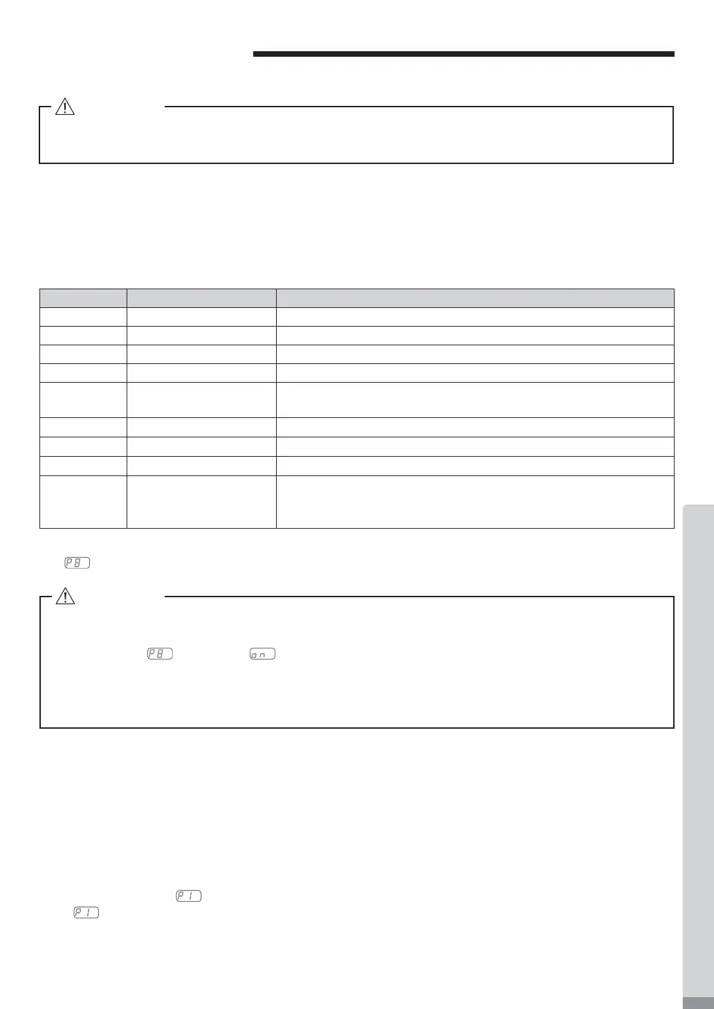
Warning Code Warning Function Trouble
A0 Motor Signal Line Motor Signal Line or Connector not connected or damaged.
A1 Low Air Pressure Low Air Pressure during motor rotation.
A2
CONTROLLER Overheat
CONTROLLER Overheat.
A3 Over Load Motor Torque Load exceeding safe limits.
A4 Emergency Stop Signal Emergency Stop Signal 'OFF (Open) ' in Emergency Stop Mode
Condition.
A5 Over Air Pressure Excessive Air Pressure
A6 Motor
Overheat The inside temperature of the motor has reached the warning level.
A7 Motor Power Line Motor Power Line or Connector not connected or damaged.
AF Temporary Motor /
Spindle Operation during
FAN malfunction
The FAN has stop, but the Motor / Spindle is temporarily operational. *
While the Warning Code " AF " is displayed, the buzzer will sound.
Table. 6
CAUTION
When the warning LED on the CONTROLLER blinks, conditions exist that could result in dangerous
operation. Check operating conditions and continue to use only after correcting the problem.
17 - 2 Detection of unsafe operating conditions
Always check the CONTROLLER, motor, spindle and the condition of the cooling air prior to operation. This will
help prevent system errors that will result in unprope
r operating conditions.
When an Error Occurs, the following events may occur :
(1) Motor stops.
(2) The Error LED (ERROR) will lights.
(3) The Error Code in Table. 6 will displayed on Digital Speed Indicator.
(4) An Error signal is output to the " ERR (PIN No. 8 : ERROR ) " of External Input / Output Connector A.
* Setting parameter
, will Change the Error Output Mode of the Error Signal. (Refer to P90 " 18 - 4 ①
Setting of Error Output Mode " section.)
* If FAN has been stopped due to a malfunction, the motor / spindle can run temporarily (Refer to P93 " 18 - 4 ⑧
Temporary Motor / Spindle Operation if FAN has Stopped (80 Square Type) " section).
CAUTION
・When the Warning LED blinks while the control is in Mode AUTO, be sure to con¿rm the Warning
Code displayed on the Digital Speed Indicator by refering to the " Warning Code " in Table 6.
・If Parameter " " is set to " " and continuous operation continues during a FAN Failure,
damage to the CONTROLLER and its internal components will occur due to excessive heat
generation while the FAN is not operating. It is critical to reduce the cutting load conditions and
operating time to minimize the risk of internal damage. to the CONTROLLER.