82
16 - 3 External Input / Output Connector Speci¿cations
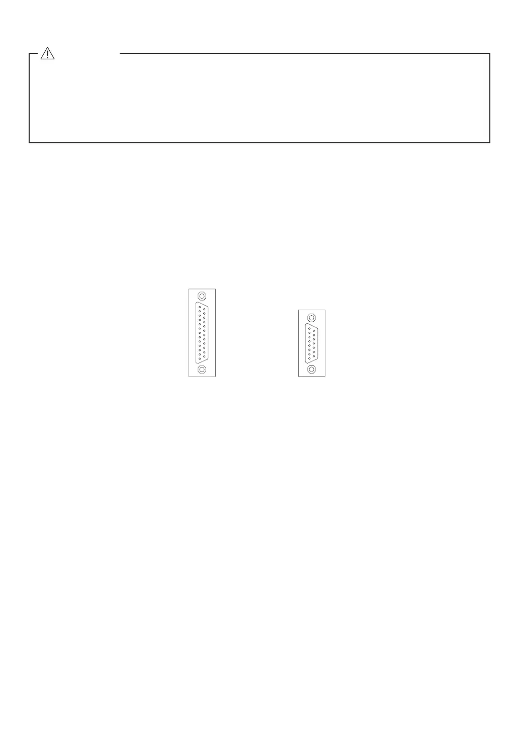
(1) External Input / Output Connector A
Plug Part Number : XM2A - 2501 OMRON (or other similar high-quality product)
Cover Part Number : XM2S - 2511 OMRON (or other similar high-quality product)
(2) External Input / Output Connector B
Plug Part Number : XM2A - 1501 OMRON (or other similar high-quality product)
Cover Part Number : XM2S - 1511 OMRON
(or other similar high-quality product)
・ Please prepare a Cover and Plug.
・ The shielding should be connected to the Cover.
・ Use the Mounting Screw " M 2.6 ".
*Fasten the Connector to the CONTROLLER using Mounting Screws (M2.6).
External Input / Output
Connector A
14
15
16
17
18
19
20
21
22
23
24
25
1
2
3
4
5
6
7
8
9
10
11
12
13
9
10
11
12
13
14
15
1
2
3
4
5
6
7
8
External Input / Output
Connector B
Fig. 36
CAUTION
・To minimize RF interference and noise, please keep the length of the cables as short as possible
and route them separately or as far away as possible from high voltage electrical cables.
・Use only shielded cables to minimize RF interference and noise. Connect the shield to the plug
cover.
・Connect the shielded line to the Input / Output connector. (The shielded line is grounded.) Do not
connect ano
ther shielded line to any externally powered instrument.
 Loading...