81
English
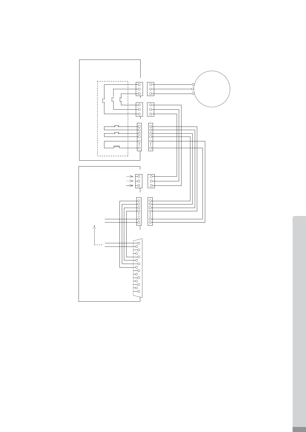
Fig. 35
* Safety Relay
If an N - O contact becomes welded, all N - C contacts will maintain a minimum distance of 0.5 mm when
the coil is not energized.
N - O contacts (Normally - opened contacts) : Motor Power Line
N - C contacts (Normally - closed contacts) : Contacts Output
* Safety of the Machines when used the Safety Relay Contacts Output
・ When input Emergency Stop Signal that is coupled to opening
the movable guard of the Industrial
Machinery, Safety Relay will operate and certainly open the Motor Power Line.
・ Contact output ((SAFE-1A) - (SAFE - 1B), (SAFE - 2A) - (SAFE - 2B)) of the " N - C Contacts" can be
used for detecting the opening of the Motor Power Line.
If " N - O contacts " become welded, contact outputs will certainly maintain OFF (Open) by Forced Guide
Mechanism. Therefore, Safe
ty Relay can be used as an opening signal of movable guard with locking
mechanism for Industrial Machinery.
12
RELAY
External Input / Output
CONNECTOR B
EMG
MOTOR - A
MOTOR - A(IN)
EMG
MOTOR - A(OUT)
RELAY - ON
DC+12V
E4000
SAFETY RELAY BOX
E4000
CONTROLLER
MOTOR
3
1
9
11
4
EMG - INA
EMG - INB
SAFE - 1A
SAFE - 1B
SAFE - 2A
SAFE - 2B
W' - phase
U' - phase
V' - phase
U' - phase
V' - phase
W - phase
U - phase
V - phase
W' - phase
・
The voltage / current speci¿cations of No. 3 (SAFE - 1A) - Pin No. 11 (SAFE - 1B) and Pin No. 4 (SAFE - 2A) -
Pin No. 12 (SAFE - 2B).
・Applied Voltage (V) ≦ DC+30V
・Working Current (Ip) ≦ 2A
・ Refer to Fig. 35 for the connection diagram.
 Loading...