60
① CONTROLLER
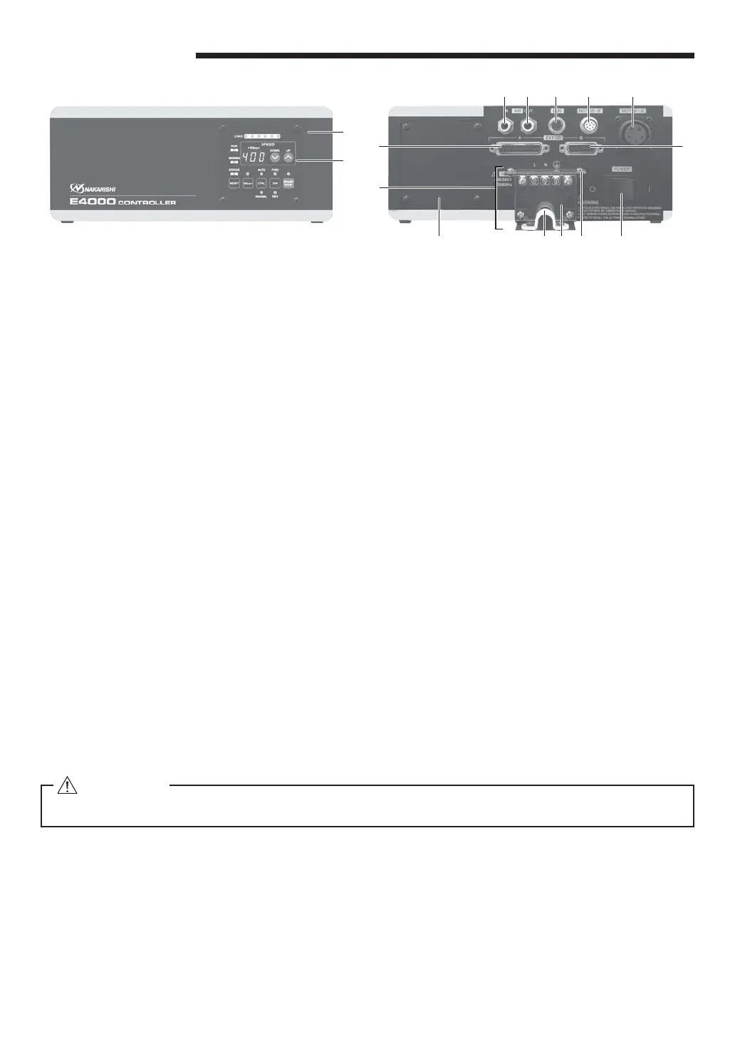
② Control Panel
Refer to P62 " 9 - 2 Control Panel Details " section.
③ External Input / Output Connector A (EXT I / O - A)
External Input / Output Connector A is for automatic control and monitoring of motor / spindle system. Refer to
P71 " 16 - 1 (1) Details of External Input / Output Connector A Signals " section.
Attach the provided Connector Cover A for safety and dust proo¿ ng, when n
ot using External Input / Output
connector A.
④ External Input / Output Connector B (EXT I / O - B)
External Input / Output Connector B is for automatic monitoring of emergency conditions. P78 " 16 - 2 (1)
Details of External Input / Output Connector B Signals " section.
Attach the provided Connector Cover B for safety and dust proo¿ ng, when not using External Input / Output
connector B.
⑤ MOTOR - A Co
nnector (MOTOR - A) : For Motor Power Line.
Connect the Motor Cord Plug (Motor Power Line) of the motor spindle.
Attach the provided Connector Cap A for safety and dust proo¿ ng, when not using MOTOR - A Connector.
⑥ MOTOR - B Connector (MOTOR - B) : For Motor Sigmal Line.
Connect the Motor Cord Plug (Motor Signal Line) of the motor spindle.
Attach the provided Connector Cap B for safety and dust proo¿
ng, when not using MOTOR - B Connector.
⑦ EMG Connector (EMG) : Emergency Stop Cord Connection to the E4000 Safety Relay Box.
Connects the Emergency Stop Cord from the CONTROLLER to the E4000 Safety Relay Box (Sold separately).
Attach the provided Connector Cap EMG for safety and dust proo¿ ng, when not using EMG Connector.
⑧ Air Input Joint (AIR - IN)
Supply clean, dry, regulated air for motor cooling.
Regulate air to between 0.2 - 0.35MPa (29.0 - 50.8psi).
When using the motor spindle for continuous use, supply the regulated air to CONTROLLER and set the air
pressure to 0.35MPa (50.8psi). The air consumption is 100Nℓ/ min when supplying air pressure of 0.35MPa
(50.8psi). Refer to P67 " 13. AIR HOSE CONNECTION " section.
CAUTION
If the air pressure is too low the CONTROLLER will not operate.
9. PARTS NAMES
Fig. 6
①
②
⑤⑥⑦⑨
⑩⑬⑫⑭⑮
⑧
④
③
⑪
Fig. 7
9 - 1 System
⑨ Air Output Joint (AIR - OUT)
Connect Air Hose to supply clean, dry, regulated air for motor and spindle cooling and purging. Refer to P67
" 13. AIR HOSE CONNECTION " section.
⑩ Main Power Switch (POWER)
ON / OFF main power source. The designation " I " Indicates ON. The designation " O " Indicates OFF.