71
English
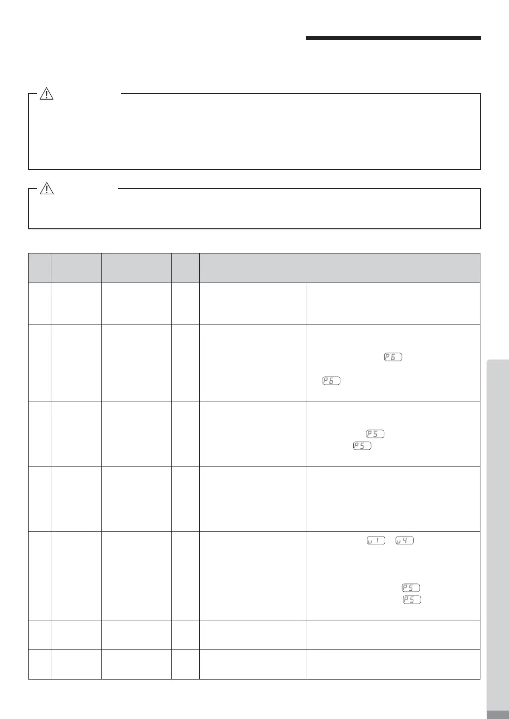
16. EXTERNAL INPUT / OUTPUT CONNECTOR
Table. 4
16 - 1 External Input / Output Connector A
(1) Details of External Input / Output Connector A Signals
・DO NOT connect any circuit other than SELV (DC+24V) (Safety Extra Low Voltage) to the External
Input / Output Connector A of the CONTROLLER. This will cause I / O board damage in the
CONTROLLER.
・Do not supply over voltage or over current into the input / output circuit. Always install a LOAD
(resistor) to the output circuit to eliminate the chance of damage to the CONTROLLER.
WARNING
CAUTION
External Input / Output Connector A DOES NOT use Pins No. 9 and No. 22. If pin No. 9 and No. 22
are connected, the CONTROLLER will be damage.
Pin
No.
Code
Function
Input /
Output
Description
1 COM_1 External Power
source for
External input
Input
DC 0V or DC+24V Power source to be used for External
Inputs Signals. (not included / prepared
by the end-user)
2 DIR_IN Rotating
Direction Setting
Input
OFF (Open) : FWD.
ON (Closed) : REV.
Controls the rotational direction of the
motor spindle.
Setting parameter
, can start with
reverse rotation. (Refer to P93 " 18 - 4
⑥
Selection of External Motor Start
Signal Control Mode " section.)
3 CNT_IN
Count Pulse
Signal for Setting
Motor Speed
Input OFF (Open) →ON (Closed)
One pulse will increase or decrease
100min
-1
(rpm) in Spindle Speed depending
on parameter
setting. (Refer to P92
" 18 - 4 ⑤
Selection of External
Speed Control Mode " section.)
4 RESET Error Release
Input ON (Closed) →OFF (Open)
Error Code can be released and the
system restarted by toggling this signal
OFF and ON.
Error will not be released until cause of
the error has been removed.
5 SEL1 Speed Point
Select 1
Input
OFF (Open)
ON (Closed)
Speed Point ( – ) can be
Selected by SEL0 and SEL1 signal
combination. P70 " 15 - 2 - 2 (4) ③ Set by
the Speed Point Signal Table 3 " section.
Need to set parameter
.
(Refer to P92 " 18 - 4 ⑤
Selection of
External Speed Control Mode
" section.)
6 RUN Rotating
Output
OFF (Open) : Stop
ON (Closed) : Rotating
Output shows that the motor is rotating.
7 DIR_OUT Rotating
Direction
Output
OFF (Open) : FWD.
ON (Closed) : REV.
Output shows the direction of the Motor is
rotating.