Chapter 2 Installing Compact FieldPoint Hardware and Software
© National Instruments Corporation 2-13 cFP-20xx and cFP-BP-x User Manual
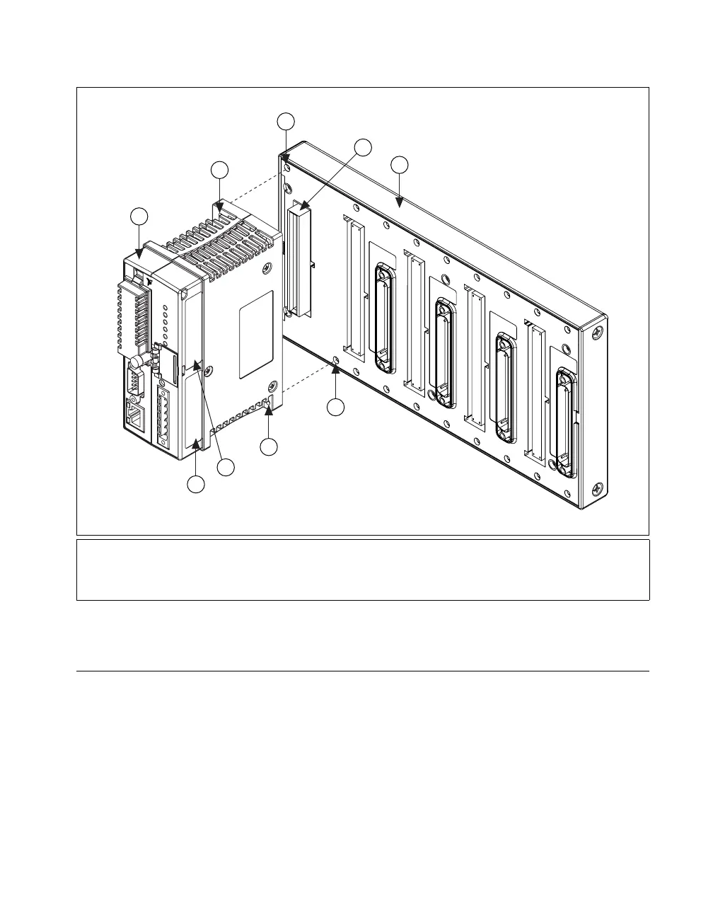
Figure 2-12. Installing the cFP-20xx Controller on the Backplane (cFP-BP-4 Shown)
Installing I/O Modules on the Backplane
1. Align the captive screws on the I/O module with the holes on the
backplane. Alignment keys on the I/O module prevent backward
insertion.
2. Press firmly to seat the I/O module on the backplane.
3. Using a number 2 Phillips screwdriver with a shank of at least 64 mm
(2.5 in.) length, tighten the captive screws to 1.1 N ⋅ m (10 lb ⋅ in.) of
torque. The nylon coating on the screws prevents them from loosening.
1cFP-20xx Controller
2 Serial Number Label
3 Write-On Address Label
4 Captive Screws
5Screw Holes
6 Card-Edge Connector
7 cFP-BP-4 Backplane
5
6
1
7
5
4
4
NATIONAL
INSTRUMENTS
2
3
 Loading...