Chapter 3 Connecting Signals
DAQCard-700 User Manual 3-2 ni.com
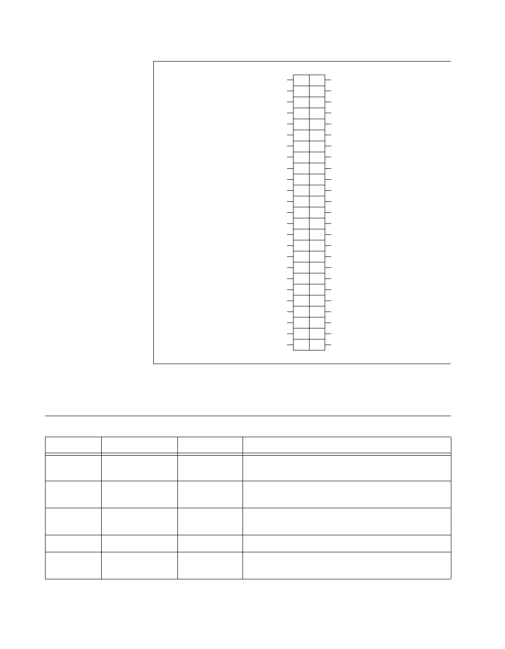
Figure 3-1. DAQCard-700 I/O Connector Pin Assignments
Signal Connection Descriptions
Pin Signal Name Direction Description
1–2 AIGND — Analog Input Ground—These pins are connected to the
AI ground signal.
3–18 ACH<0..15> Input Analog Input Channels 0 through 15—These channels are
available in single-ended mode.
19 DGND — Digital Ground—This pin is connected to the digital ground
signal.
20–21 NC — Not Connected—These pins are not connected.
22–29 DIN<0..7> Input Input Digital Data Lines 0 through 7—DIN7 is the MSB
(most significant bit), DIN0 the LSB (least significant bit).
2
4
6
8
10
12
14
16
18
20
22
24
26
28
30
32
34
36
38
40
42
44
46
48
50
1
3
5
7
9
11
13
15
17
19
21
23
25
27
29
31
33
35
37
39
41
43
45
47
49
AIGND
ACH0
ACH1
ACH2
ACH3
ACH4
ACH5
ACH6
ACH7
DGND
NC
DIN1
DIN3
DIN5
DIN7
DOUT1
DOUT3
DOUT5
DOUT7
EXTINT*
OUT0
OUT1
CLK1
GATE2
+5 V
AIGND
ACH8
ACH9
ACH10
ACH11
ACH12
ACH13
ACH14
ACH15
NC
DIN0
DIN2
DIN4
DIN6
DOUT0
DOUT2
DOUT4
DOUT6
OUT1*
EXTCONV*
GATE0
GATE1
OUT2
CLK2
DGND
 Loading...