Chapter 3 Connecting Signals
DAQCard-700 User Manual 3-14 ni.com
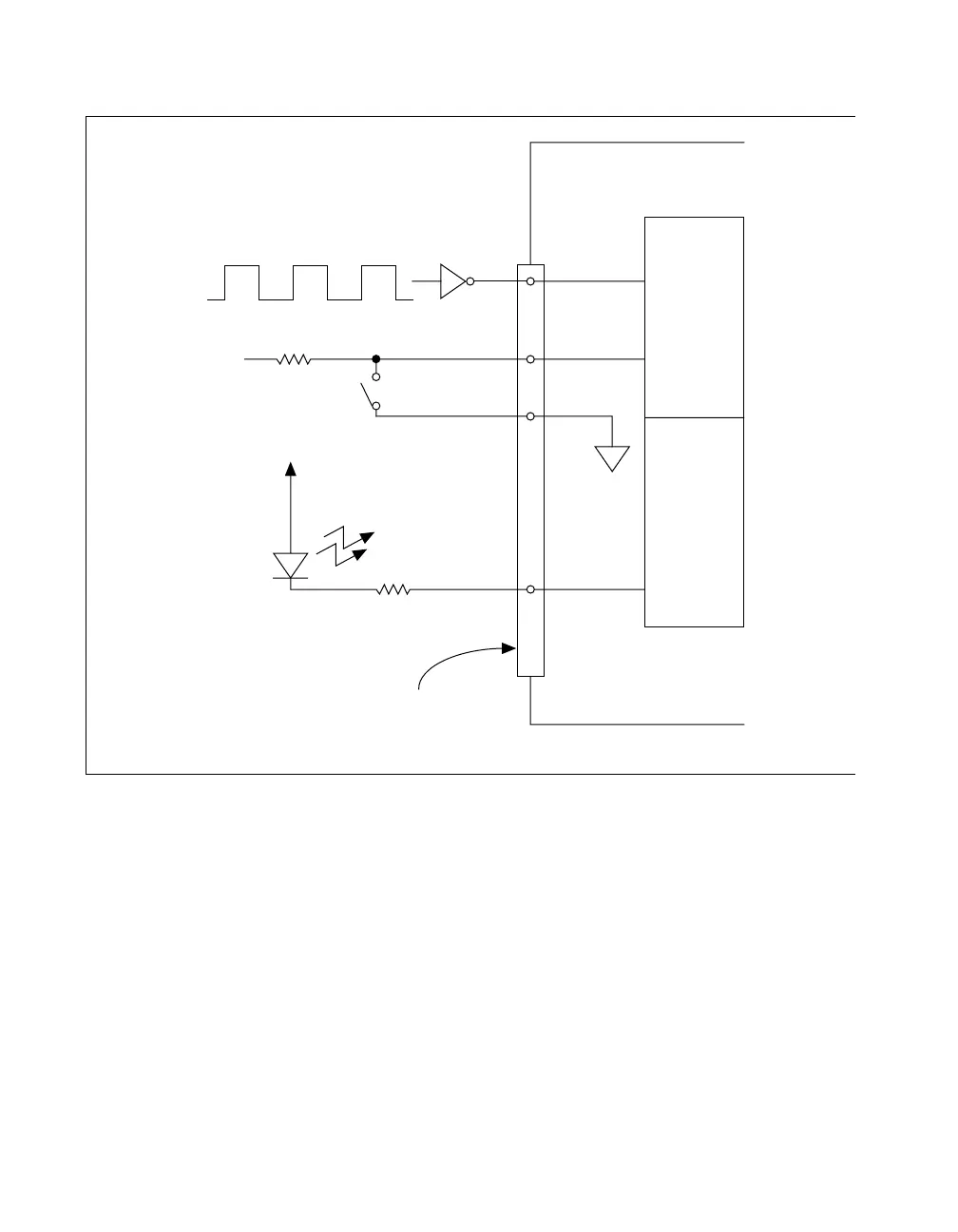
Figure 3-6. Digital I/O Signal Connections
Connecting Power
Pin 49 of the I/O connector sends +5 V from the PCMCIA I/O channel
power supply. This pin is referenced to DGND and can be used to power
external digital circuitry that draws up to 1 A. Pin 49 is connected to a 1 A
resettable fuse on the card. The actual current available from this signal
may be less than 1 A, depending on the computer. Notice also that any
current drawn from this line adds to the power requirements from the
computer.
Digital
Input
Port
Digital
Output
Port
TTL Signal
+5 V
+5 V
LED
I/O Connector
DAQCard-700
30 DOUT0
DGND
19
29 DIN7
22 DIN0
 Loading...