Chapter 4 Theory of Operation
© National Instruments Corporation 4-5 DAQCard-700 User Manual
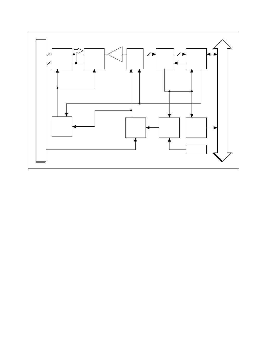
Figure 4-3. Analog Input and DAQ Circuitry Block Diagram
Analog Input Circuitry
The AI circuitry consists of an input multiplexer, a software-selectable gain
stage, and a 12-bit sampling ADC. The 12-bit output is sign-extended to
16 bits, then stored in a FIFO memory that is 512 words deep.
The input multiplexer stage is made up of two CMOS AI multiplexers. In
single-ended mode, the input multiplexers switch between 16 AI channels
(channels 0 through 15). In DIFF input mode, one of the input multiplexers
switches between eight differential pairs (channels 0 and 8, 1 and 9, and so
on). With the input multiplexer stage, input overvoltage protection of
±30Visavailable,poweredonoroff.
The DAQCard-700 uses a 12-bit successive-approximation ADC.
Software-selectable gains of 1, 0.5, and 0.25 for the input signal combined
with the ADC fixed input range of ± 10 V yield three useful AI signal
ranges. These ranges are ±10 V, ± 5 V, and ± 2.5 V.
When an A/D conversion is complete, the ADC clocks the result into the
A/D FIFO. The A/D FIFO is 16 bits wide and 512 words deep. This FIFO
Buffer
PCMCIA I/O Channel
I/O Connector
512-Word
FIFO,
Sign
Extension
12-Bit
Sampling
ADC
Instrumentation
Amplifier
Input
Mux1 Dual
(8-Channel
Single-
Ended)
Input
Mux2
(4-Channel)
PCMCIA
I/O Channel
Interface
Interrupt
Interface
A/D Timing
MSM82C54
Scanning
Counter
1MHz
A/D
Data
Data
1612
A/D RD
CLK0
OUT0
EXTCONV*
8
8
 Loading...