Chapter 3 Connecting Signals
© National Instruments Corporation 3-3 DAQCard-700 User Manual
The connector pins can be grouped into AI signal pins, DIO signal pins, and
TIO signal pins. Signal connection guidelines for each of these groups are
included in the following pages.
Connecting Analog Input Signals
Pins 1 through 18 are AI signal pins for the ADC. Pins 1 and 2, named
AIGND, are an analog common signal. You can use these pins for a general
analog power ground tie to the DAQCard-700. Pins 3 through 18 are the
ACH<0..15> signal pins. These pins are tied to the AI channels of the
DAQCard-700 through 4.7 kΩ series resistors. These resistors limit the
input current to the multiplexer. Refer to Appendix A, Specifications,for
input ranges and maximum ratings for the analog inputs, ACH<0..15>.
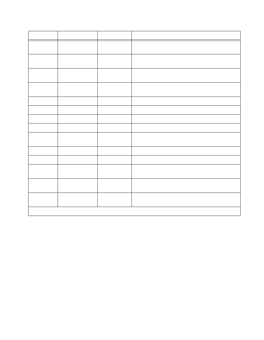
30–37 DOUT<0..7> Output Output Digital Data Lines 0 through 7—DOUT7 is the MSB,
DOUT0 the LSB.
38 OUT1* Output Counter 1 Output—This pin is the inversion of counter 1
output.
39 EXTINT* Input External Interrupt—This pin is used for input of the external
interrupt signal.
40 EXTCONV* Input External Control—This pin is used for input of the external
control signal to trigger A/D conversions.
41 OUT0 Output Counter 0 Output—This pin is the output of counter 0.
42 GATE0 Input Counter 0 Gate Input—This pin is the gate input for counter 0.
43 OUT1 Output Counter 1 Output—This pin is the output of counter 1.
44 GATE1 Input Counter 1 Gate Input—This pin is the gate input for counter 1.
45 CLK1 Input Counter 1 Clock Input—This pin is the clock input for
counter 1.
46 OUT2 Output Counter 2 Output—This pin is the output of counter 2.
47 GATE2 Input Counter 2 Gate Input—This pin is the gate input for counter 2.
48 CLK2 Input Counter 2 Clock Input—This pin is the clock input for
counter 2.
49 +5 V Output +5 Volts—This pin provides +5 VDC. The +5 V supply is
fused at 1 A, which is the maximum current available.
50 DGND — Digital Ground—This pin is connected to the digital ground
signal.
* Indicates that the signal is active low.
Pin Signal Name Direction Description
 Loading...