Appendix A Device-Specific Information
© National Instruments A-7 X Series User Manual
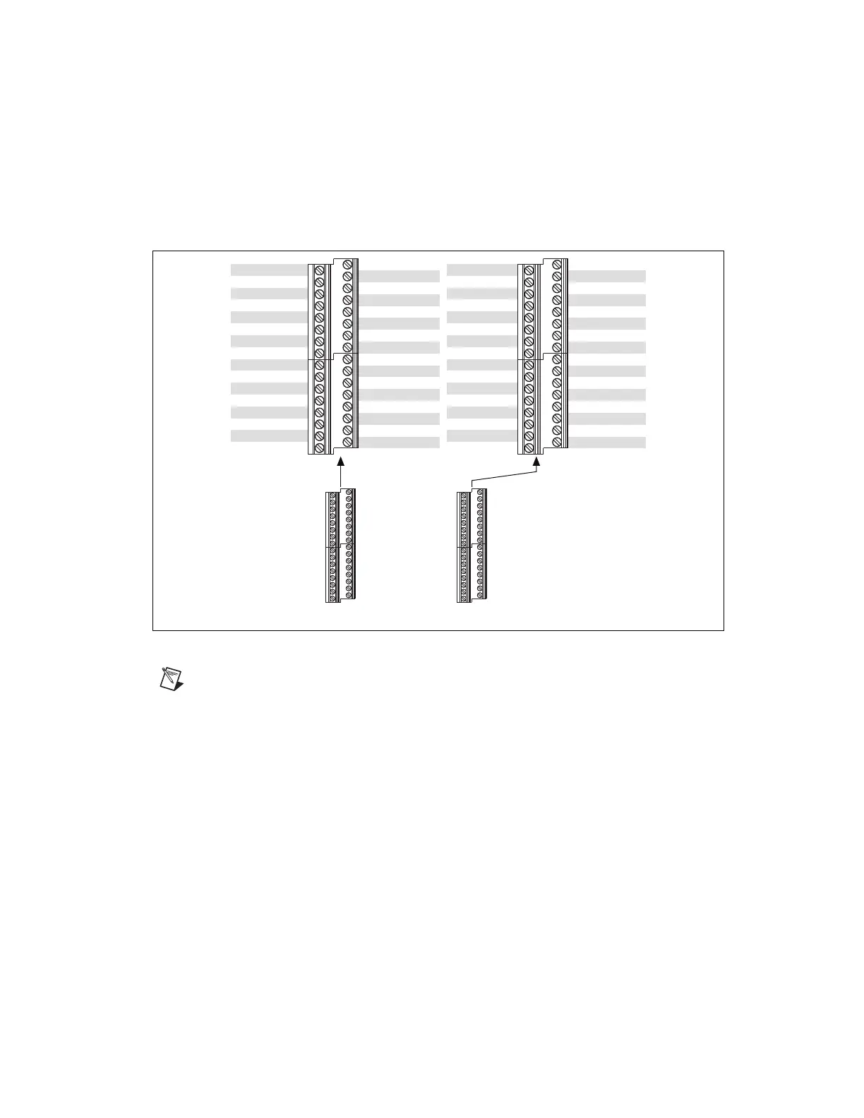
Figure A-3 shows the pinout of the NI USB-6341. For a detailed
description of each signal, refer to the I/O Connector Signal Descriptions
section of Chapter 3, Connector and LED Information.
Figure A-3. NI USB-6341 Pinout
Note
Refer to Table 7-10, X Series USB Screw Terminal Device Default NI-DAQmx
Counter/Timer Pins, for a list of the default NI-DAQmx counter/timer pins for this device.
For more information about default NI-DAQmx counter inputs, refer to Connecting
Counter Signals in the NI-DAQmx Help or the LabVIEW Help.
NI 6321/6341 Specifications
Refer to the NI 632x Specifications for more detailed information about the
NI 6321 device. Refer to the NI 634x Specifications for more detailed
information about the NI 6341 device.
NI 6321/6341 Accessory and Cabling Options
NI offers a variety of accessories and cables to use with your DAQ device.
Refer to the Cables and Accessories section of Chapter 2, DAQ System
Overview, for more information.
17
18
19
20
21
22
23
24
25
26
27
28
29
30
31
32
AI 4 (AI 4+)
AI 12 (AI 4–)
AI GND
AI 5 (AI 5+)
AI 13 (AI 5–)
AI GND
AI 6 (AI 6+)
AI 14 (AI 6–)
AI GND
AI 7 (AI 7+)
AI 15 (AI 7–)
AI GND
NC
AI GND
AO 1
AO GND
AI 0 (AI 0+)
AI 8 (AI 0–)
AI GND
AI 1 (AI 1+)
AI 9 (AI 1–)
AI GND
AI 2 (AI 2+)
AI 10 (AI 2–)
AI GND
AI 3 (AI 3+)
AI 11 (AI 3–)
AI GND
AI SENSE
AI GND
AO 0
AO GND
1
2
3
4
5
6
7
8
9
10
11
12
13
14
15
16
81
82
83
84
85
86
87
88
89
90
91
92
93
94
95
96
PFI 8/P2.0
D GND
PFI 9/P2.1
D GND
PFI 10/P2.2
D GND
PFI 11/P2.3
D GND
PFI 12/P2.4
D GND
PFI 13/P2.5
D GND
PFI 14/P2.6
D GND
PFI 15/P2.7
+5 V
P0.0
P0.1
P0.2
P0.3
P0.4
P0.5
P0.6
P0.7
PFI 0/P1.0
PFI 1/P1.1
PFI 2/P1.2
PFI 3/P1.3
PFI 4/P1.4
PFI 5/P1.5
PFI 6/P1.6
PFI 7/P1.7
65
66
67
68
69
70
71
72
73
74
75
76
77
78
79
80
NC = No Connect
Artisan Technology Group - Quality Instrumentation ... Guaranteed | (888) 88-SOURCE | www.artisantg.com
 Loading...


