Appendix A Device-Specific Information
© National Instruments Corporation A-91 E Series User Manual
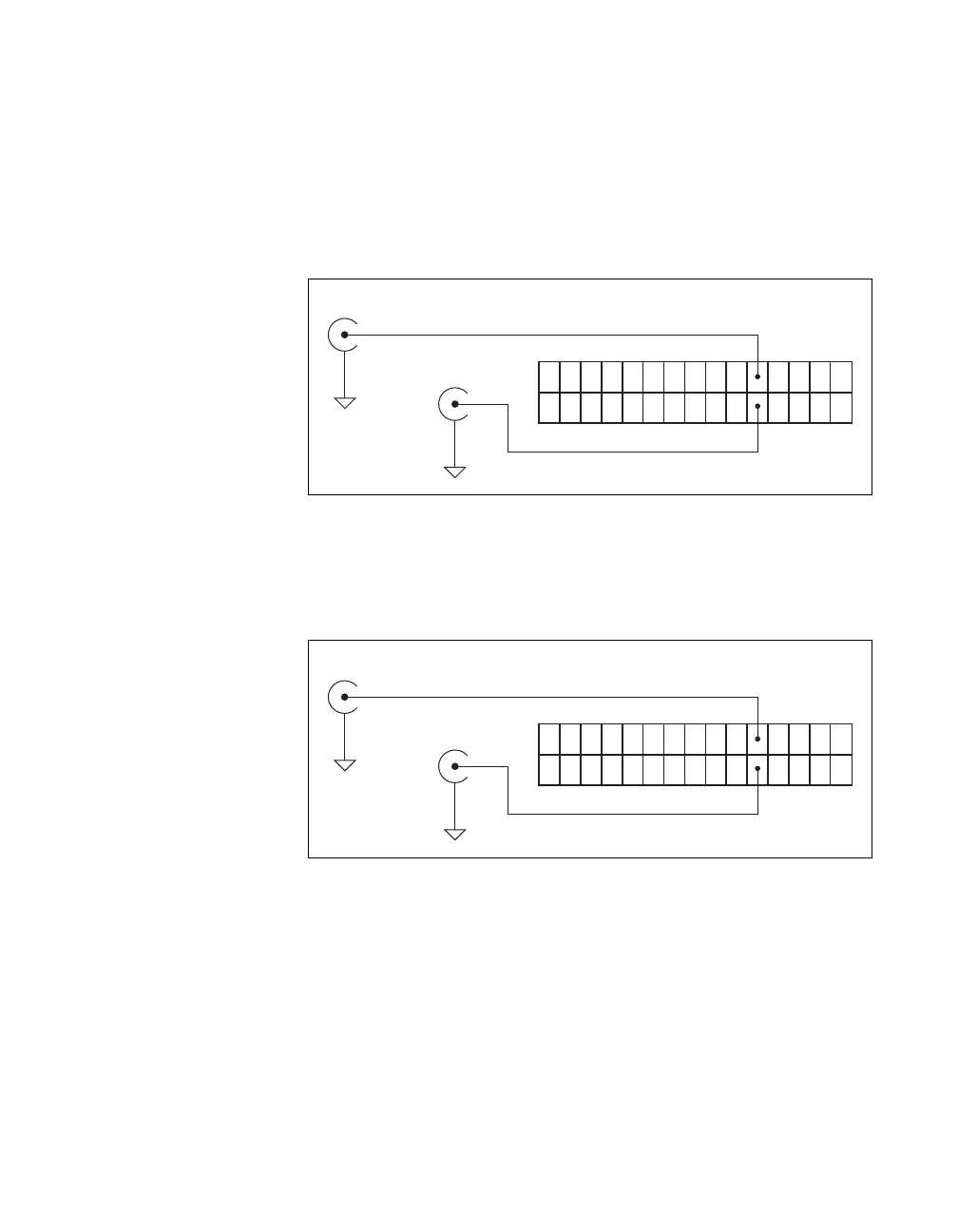
User <1..2>
The User <1..2> signals connect directly from a screw terminal to a BNC.
They allow you to use a BNC connector for a digital or timing I/O signal of
your choice. The USER 1 BNC is internally connected to pin 21 and the
USER 2 BNC is internally connected to pin 22 on the 30-pin I/O connector.
Figure A-81 shows the connection of the User <1..2> BNCs.
Figure A-81. User <1..2> BNCs
Figure A-82 shows another example of how to use the User <1..2> BNCs.
To access the Ctr1Out signal from a BNC, connect pin 21
(USER 1) to pin 17 (CTR 1 OUT) with a wire.
Figure A-82. User <1..2> BNC Example
Other Signals
You can access other signals on BNC DAQPads through a 30-pin
Combicon connector.
To connect to one of these signals, use a small screwdriver to press down
the orange spring release button at a terminal and insert a wire. Releasing
the orange spring release button will lock the wire securely in place.
User 1 BNC
User 2 BNC
Pin 21
Pin 22
30-Pin I/O Connector
D GND
D GND
User 1 BNC
User 2 BNC
Pin 21
Pin 22
30-Pin I/O Connector
D GND
D GND

 Loading...


