Appendix A Device-Specific Information
© National Instruments Corporation A-95 E Series User Manual
Because the NI 6070E/6071E have no DIP switches, jumpers, or
potentiometers, you can easily configure and calibrate them through
software.
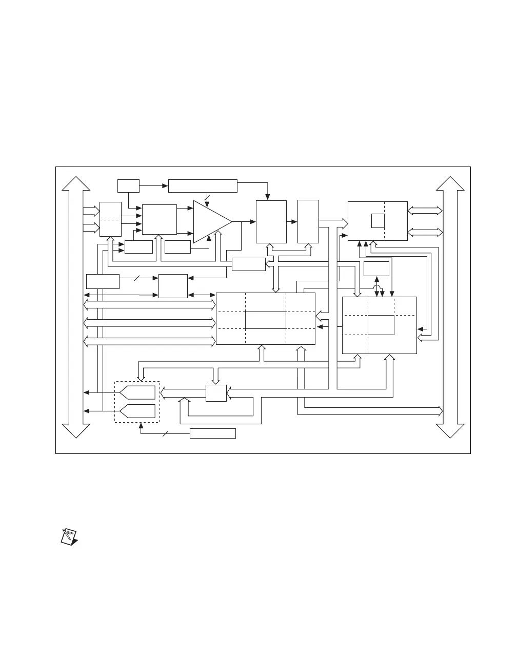
NI 6070E/6071E Block Diagram
Figure A-85 shows a block diagram of the NI PCI/PXI-6070E and
NI PCI-6071E.
Figure A-85. NI 6070E/6071E Block Diagram
NI PCI/PXI-6070E Pinout
Figure A-86 shows the NI 6070E device pinout.
Note Some hardware accessories may not yet reflect the NI-DAQmx terminal names. If
you are using an E Series device in Traditional NI-DAQ (Legacy), refer to Table 1-5,
Terminal Name Equivalents, for the Traditional NI-DAQ (Legacy) signal names.
AO Control
Mux Mode
Selection
Switches
Timing
PFI/Trigger
Digital I/O (8)
12-Bit
Sampling
A/D
Converter
EEPROM
NI-PGIA
Gain
Amplifier
Voltage
REF
Calibration
DACs
DAC0
DAC1
DAQ - STC
Trigger
(8)*
(8)*
AI Control
Address/
Data
Control
Analog
Input
Control
EEPROM
Control
MIO
Interface
MINI-
MITE
Generic
Bus
Interface
IRQ
DMA
Address (5)
DMA
Interface
Analog
Output
Control
PCI
Bus
Interface
Calibration DACs
Analog
PXI Bus
Muxes
3
+
–
Trigger Level
DACs
Analog
Trigger
Circuitry
Calibration
Mux
2
Trigger
Counter/
Timing I/O
Digital I/O
Analog Input
Timing/Control
Analog Output
Timing/Control
DMA/
Interrupt
Request
Bus
Interface
RTSI Bus
Interface
Data(16)
ADC
FIFO
DAC
FIFO
6
Data (16)
I/O
Bus
Interface
I/O Connector
*(32) for the PXI-6071E
RTSI
Dither
Circuitry
DAQ-STC
Bus
Interface
Configuration
Memory
 Loading...


