Appendix B I/O Connector Pinouts
© National Instruments Corporation B-7 E Series User Manual
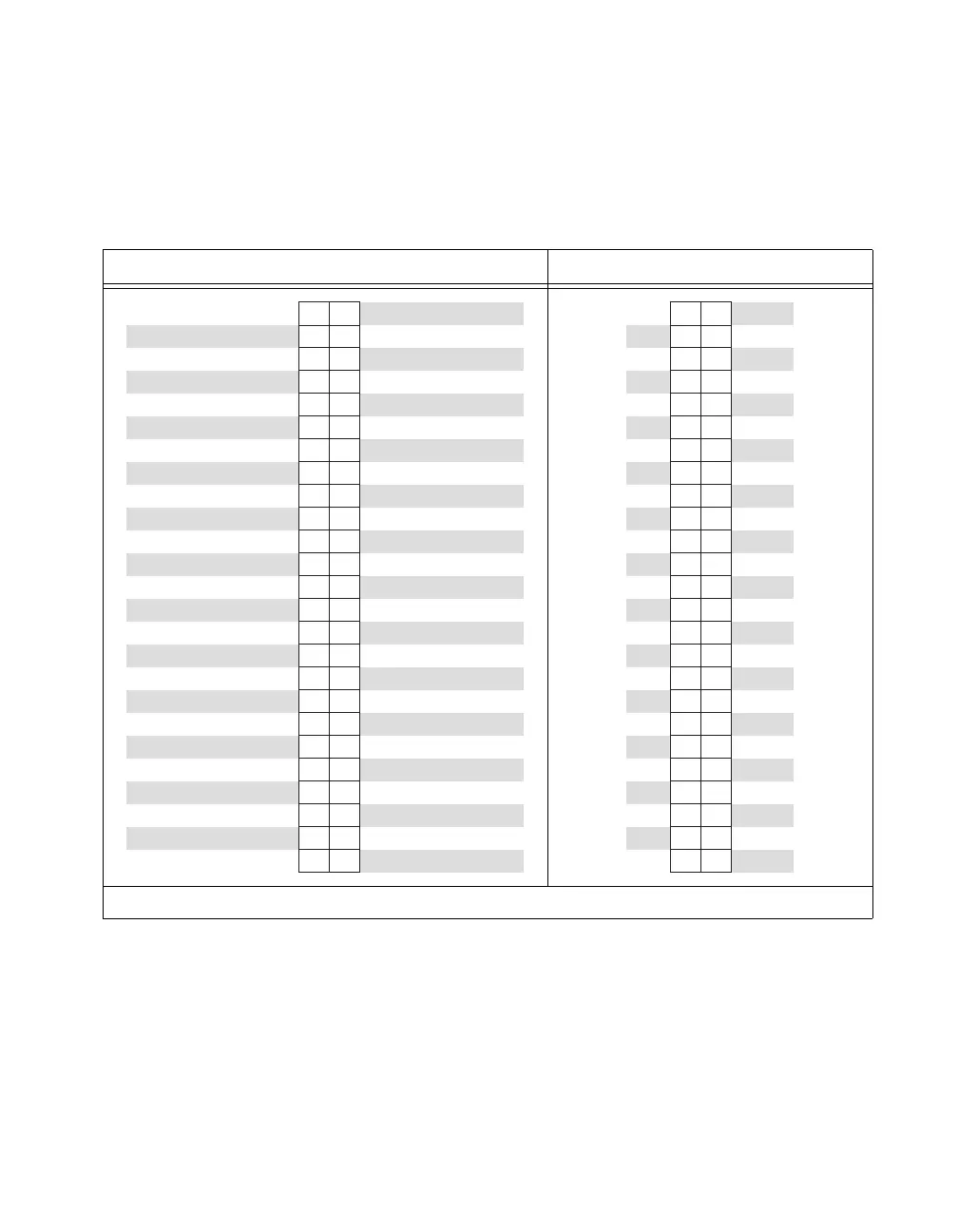
100-50-50-Pin Extended DIO I/O Connector Pinout
When you use the NI 6025E with an R1005050 cable assembly, the signals
appear on two 50-pin connectors. Figure B-3 shows the pinouts of the
50-pin connectors.
Figure B-3. 100-50-50-Pin Extended DIO I/O Connector Pinout
Positions 1–50 Connector Positions 51–100 Connector
1
No connects appear on pins 20 through 23 of devices that do not support AO or use an external reference.
CTR 0 OUT
PFI 8/CTR 0 SRC
PFI 6/AO START TRIG
CTR 1 OUT
PFI 3/CTR 1 SRC
PFI 1/AI REF TRIG
EXT STROBE
+5 V
D GND
P0.3
P0.2
P0.1
P0.0
AO GND
1
AO 1
1
AI SENSE
AI 7
AI 6
AI 5
AI 4
AI 3
AI 2
AI 1
AI 0
AI GND
FREQ OUT
PFI 7/AI SAMP CLK
PFI 5/AI SAMP CLK
PFI 2/AI CONV CLK
PFI 0/AI START TRIG
AI HOLD COMP
+5 V
PFI 9/CTR 0 GATE
PFI 4/CTR 1 GATE
P0.7
P0.6
P0.5
P0.4
D GND
AO EXT REF
1
AO 0
1
AI 15
AI 14
AI 13
AI 12
AI 11
AI 10
AI 9
AI 8
AI GND
49
47
45
43
41
39
37
35
33
31
29
27
25
23
21
19
17
15
13
11
9
7
5
3
1
50
48
46
44
42
40
38
36
34
32
30
28
26
24
22
20
18
16
14
12
10
8
6
4
2
+5 V
P1.0
P1.1
P1.2
P1.3
P1.4
P1.5
P1.6
P1.7
P2.0
P2.1
P2.2
P2.3
P2.4
P2.5
P2.6
P2.7
P3.0
P3.1
P3.2
P3.3
P3.4
P3.5
P3.6
P3.7
D GND
D GND
D GND
D GND
D GND
D GND
D GND
D GND
D GND
D GND
D GND
D GND
D GND
D GND
D GND
D GND
D GND
D GND
D GND
D GND
D GND
D GND
D GND
D GND
D GND
49
47
45
43
41
39
37
35
33
31
29
27
25
23
21
19
17
15
13
11
9
7
5
3
1
50
48
46
44
42
40
38
36
34
32
30
28
26
24
22
20
18
16
14
12
10
8
6
4
2
 Loading...


