Chapter 1 DAQ System Overview
E Series User Manual 1-12 ni.com
D GND — — Digital Ground—These pins supply the reference for the
digital signals at the I/O connector as well as the +5 VDC
supply. All three ground references—AI GND, AO GND,
and D GND—are connected on the device.
P0.<0..7> D GND Input or
Output
Digital I/O Signals—You can individually configure each
signal as an input or output. P0.6 and P0.7 can also control
the up/down signal of Counters 0 and 1, respectively.
AO EXT REF AO GND Input External Reference—This is the external reference input
for the AO circuitry.
P1.<0..7> D GND Input or
Output
NI 6025E only—Port 1 bidirectional digital data lines for
the 82C55A programmable peripheral interface. P1.7 is the
most significant bit (MSB). P1.0 is the least significant bit
(LSB).
P2.<0..7> D GND Input or
Output
NI 6025E only—Port 2 bidirectional digital data lines for
the 82C55A programmable peripheral interface. P2.7 is the
MSB. P2.0 is the LSB.
P3.<0..7> D GND Input or
Output
NI 6025E only—Port 3 bidirectional digital data lines for
the 82C55A programmable peripheral interface. P3.7 is the
MSB. P3.0 is the LSB.
+5 V D GND Output +5 V Power Source—These pins provide +5 V power.
AI HOLD COMP D GND Output AI Hold Complete Event Signal—When enabled, this
signal pulses once for each A/D conversion in sampling
mode. The low-to-high edge indicates when the input
signal can be removed from the input or switched to
another signal.
EXT STROBE D GND Output External Strobe Signal—You can toggle this output with
software controls to latch signals or trigger events on
external devices. This functionality is not available in
LabVIEW or NI-DAQ. EXT STROBE is used for
controlling SCXI chassis, and it is not a general-purpose
signal. If you want to use or control this signal, you must
perform register-level programming.
PFI 0/AI START
TRIG
D GND Input PFI 0—As an input, this pin is a programmable function
interface (PFI).
Output AI Start Trigger Signal—As an output, this pin is the
ai/StartTrigger signal. In post-trigger DAQ sequences, a
low-to-high transition indicates the initiation of the
acquisition sequence. In applications with pre-trigger
samples, a low-to-high transition indicates the initiation of
the pre-trigger samples.
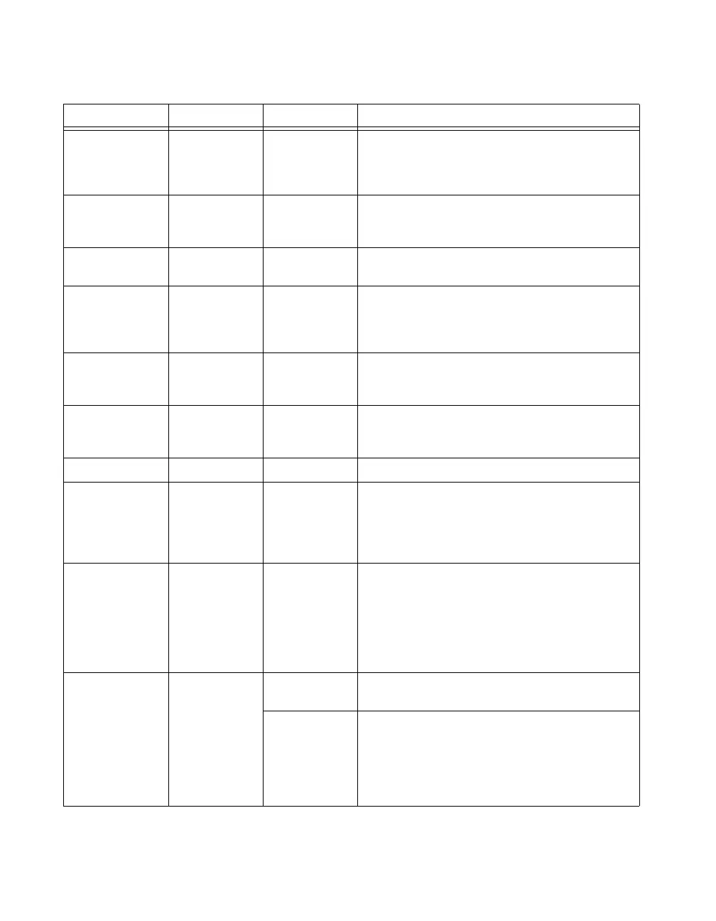
Table 1-4. I/O Connector Signal Descriptions (Continued)
Signal Name Reference Direction Description
 Loading...


