Chapter 1 DAQ System Overview
© National Instruments Corporation 1-13 E Series User Manual
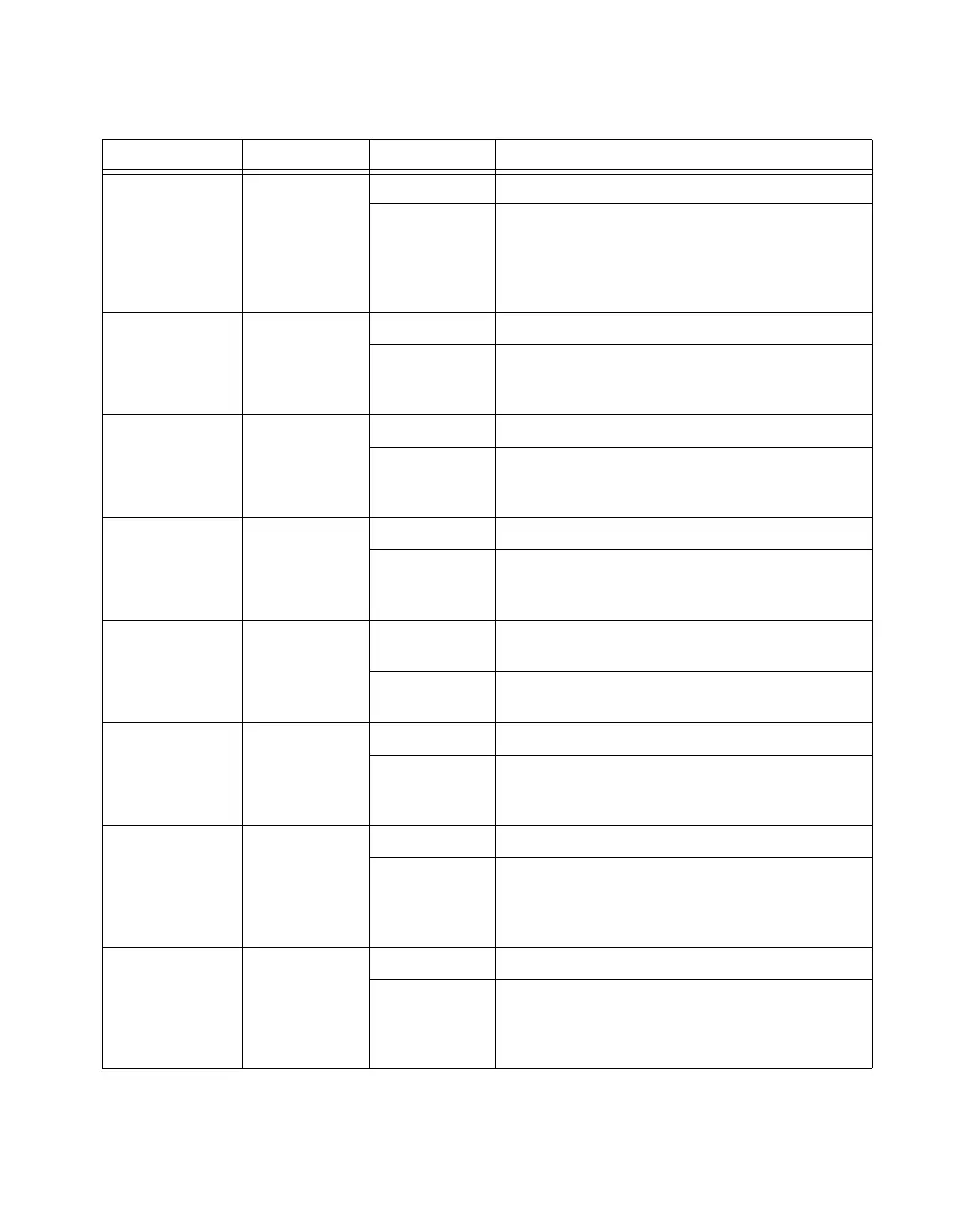
PFI 1/AI REF
TRIG, PFI 1
D GND Input PFI 1—As an input, this pin is a PFI.
Output AI Reference Trigger Signal—As an output, this pin is
the ai/ReferenceTrigger signal. In applications with
pre-trigger samples, a low-to-high transition indicates the
initiation of the post-trigger samples. AI Reference Trigger
is not used in applications with post-trigger samples.
PFI 2/AI CONV
CLK
D GND Input PFI 2—As an input, this pin is a PFI.
Output AI Convert Clock Signal—As an output, this pin is the
ai/ConvertClock signal. A high-to-low edge on AI CONV
indicates that an A/D conversion is occurring.
PFI 3/CTR 1 SRC D GND Input PFI 3—As an input, this pin is a PFI.
Output Counter 1 Source Signal—As an output, this pin is the
Ctr1Source signal. This signal reflects the actual source
connected to the general-purpose Counter 1.
PFI 4/CTR 1
GATE
D GND Input PFI 4—As an input, this pin is a PFI.
Output Counter 1 Gate Signal—As an output, this pin is the
Ctr1Gate signal. This signal reflects the actual gate signal
connected to the general-purpose Counter 1.
CTR 1 OUT D GND Input CTR 1 OUT—As an input, this pin can be used to route
signals directly to the RTSI bus.
Output Counter 1 Output Signal—As an output, this pin emits
the Ctr1InternalOutput signal.
PFI 5/AO SAMP
CLK
D GND Input PFI 5—As an input, this pin is a PFI.
Output AO Sample Clock Signal—As an output, this pin is the
ao/SampleClock signal. A high-to-low edge on AO SAMP
indicates that the AO primary group is being updated.
PFI 6/AO START
TRIG
D GND Input PFI 6—As an input, this pin is a PFI.
Output AO Start Trigger Signal—As an output, this pin is the
ao/StartTrigger signal. In timed AO sequences, a
low-to-high transition indicates the initiation of the
waveform generation.
PFI 7/AI SAMP
CLK
D GND Input PFI 7—As an input, this pin is a PFI.
Output AI Sample Clock Signal—As an output, this pin is the
ai/SampleClock signal. This pin pulses once at the start of
each AI sample in the interval sample. A low-to-high
transition indicates the start of the sample.
Table 1-4. I/O Connector Signal Descriptions (Continued)
Signal Name Reference Direction Description
 Loading...


