PXIe-4466/4467 Calibration Procedure
© National Instruments Corporation 11
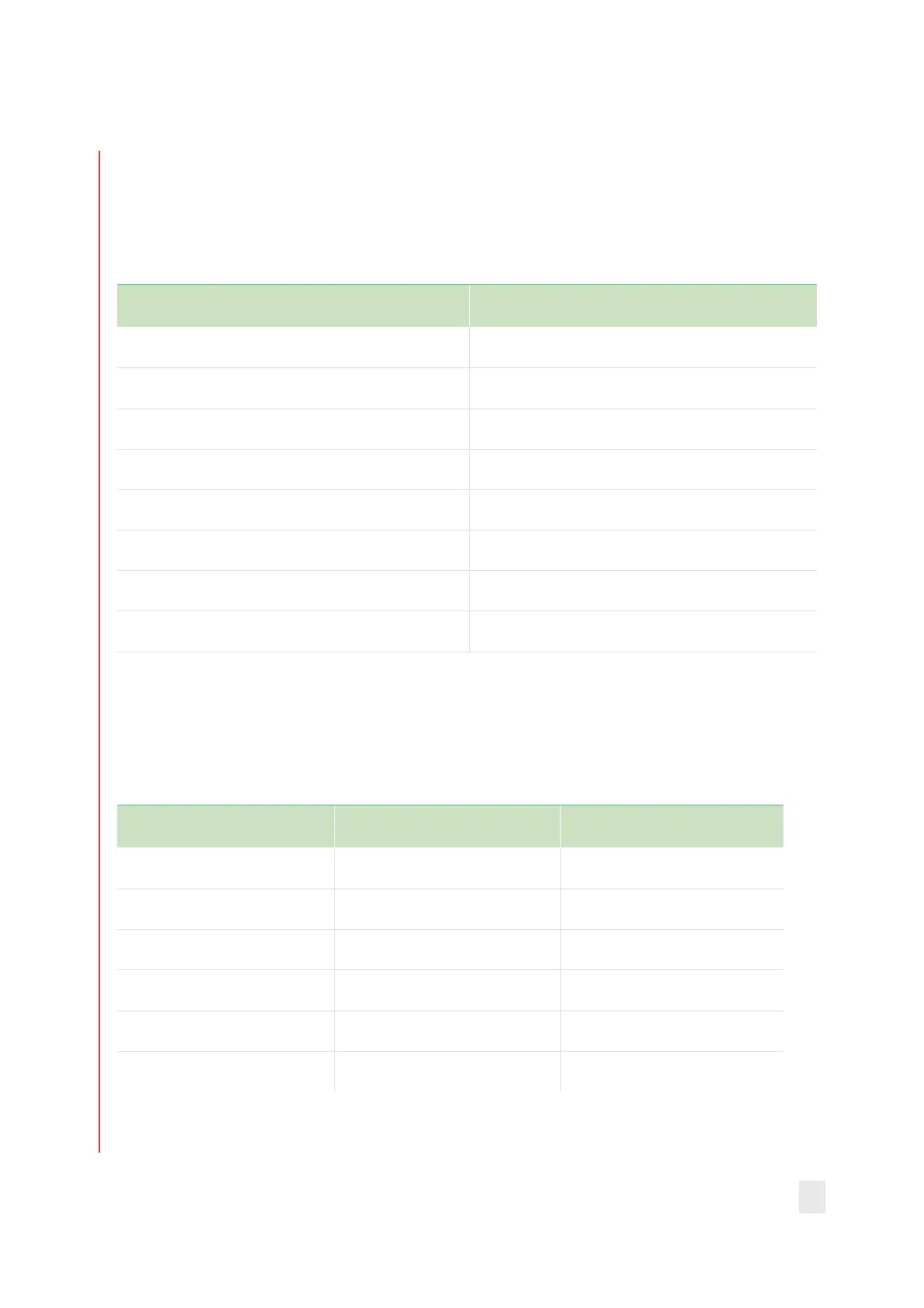
3. Create and configure an AI voltage task on the DUT as shown in
Table 2.
Table 2: AI Offset Verification Configuration
Configuration Value
Physical channels Dev_name/aix
Gain* Gain from Table 1
Coupling DC
Terminal configuration Pseudodifferential
Excitation (IEPE) 0 (A)
Acquisition mode Finite number of samples
Rate 250000
Samples per channel 125000
* As you configure the AI voltage task, refer to Table 3 for the maximum and minimum
voltages to specify when creating the task to ensure the specified gain range is used on
the module. The module automatically selects the gain range based on the maximum and mini
voltages you supply when you create the task.
Table 3: Gain Range and Corresponding Max and Min Voltages
Desired Gain Range (dB) Max Voltage (V) Min Voltage (V)
-20 42.4 -42.4
-10 31.6 -31.6
0 10.0 -10.0
10 3.16 -3.16
20 1.00 -1.00
30 0.316 -0.316
 Loading...


