69
Note: Your machine may not match the image. For reference only.
1. 'LVFRQQHFWDQGUHFRQQHFWWKH$&$GDSWHUIURPWKHZDOORXWOHWWRWXUQ
the power off and on. Push QuickStart and verify that the console shows
that the default resistance level is 4. Set the resistance to the highest
level.
Disconnect all power and allow to sit for 5 minutes.
2. Carefully remove the Shrouds. Refer to the “Replace the Shrouds”
procedure in this manual.
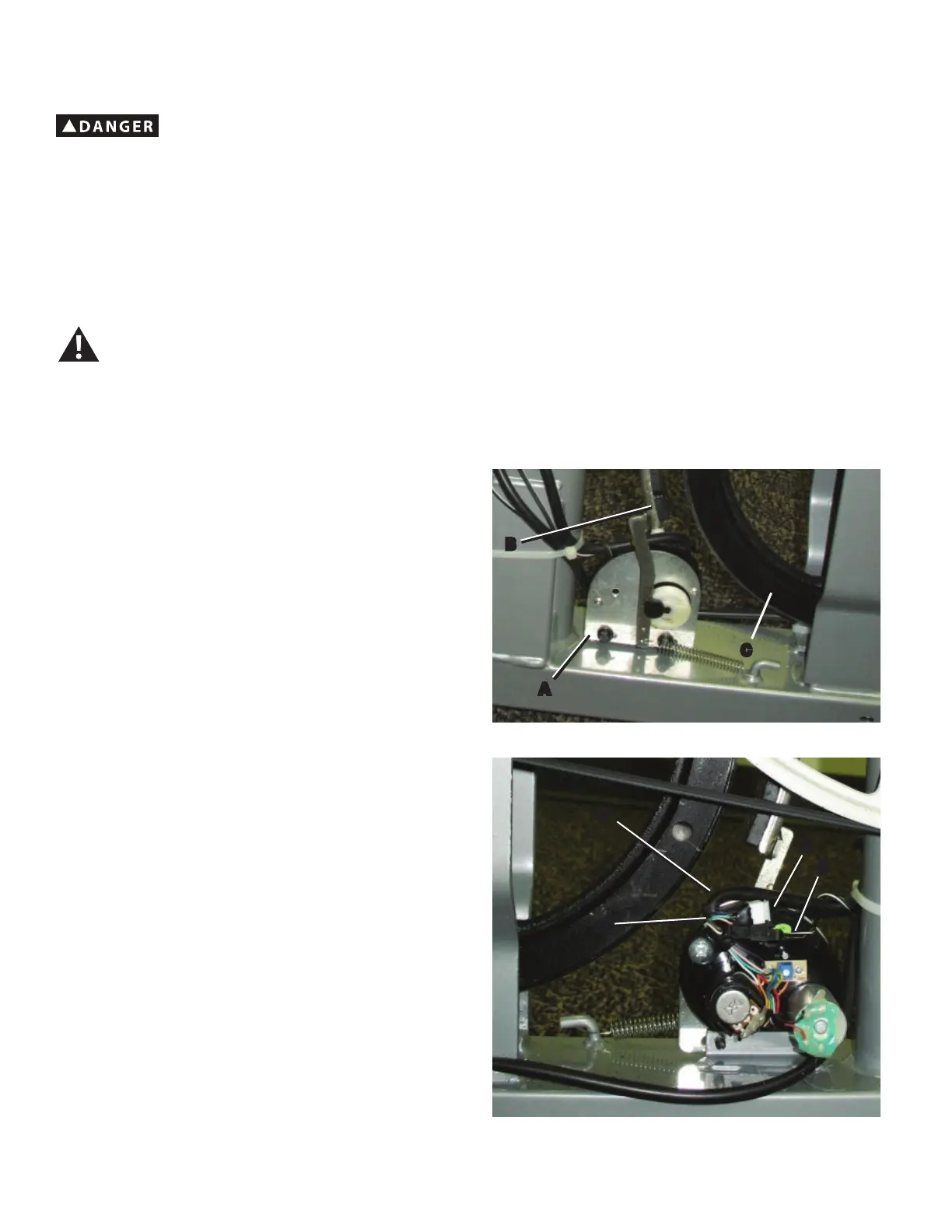
3. Measure and mark the position of the Servo Motor bracket (A) on the
Main Frame.
4. Insert 2.5” x 10” cardboard between the Brake Magnet (B) and the
Flywheel (C), and tape the cardboard to the Brake Magnet.
Note: Be sure the cardboard covers all of the Brake Magnet.
5. Observe the cable routing to the wiring harness (F) on your machine.
'LVFRQQHFWWKH6SHHG6HQVRU&DEOH'DQG6HUYR&RQWURO:LUH(IURP
the wiring harness.
NOTICE: It is necessary to remove the Shrouds for this procedure. Refer to the “Replace the Shrouds” procedure.
It may be necessary to adjust the brake tension at the end of this procedure. Refer to the “Set the Brake Tension” procedure.
!
To reduce the risk of electrical shock or unsupervised usage of the equipment, always unplug the power cord from the
wall outlet and the machine and wait 5 minutes before cleaning, maintaining or repairing the machine. Place the power
cord in a secure location.
C
A
B
D
F
E
G

 Loading...