56 Installing the Water Heater
●
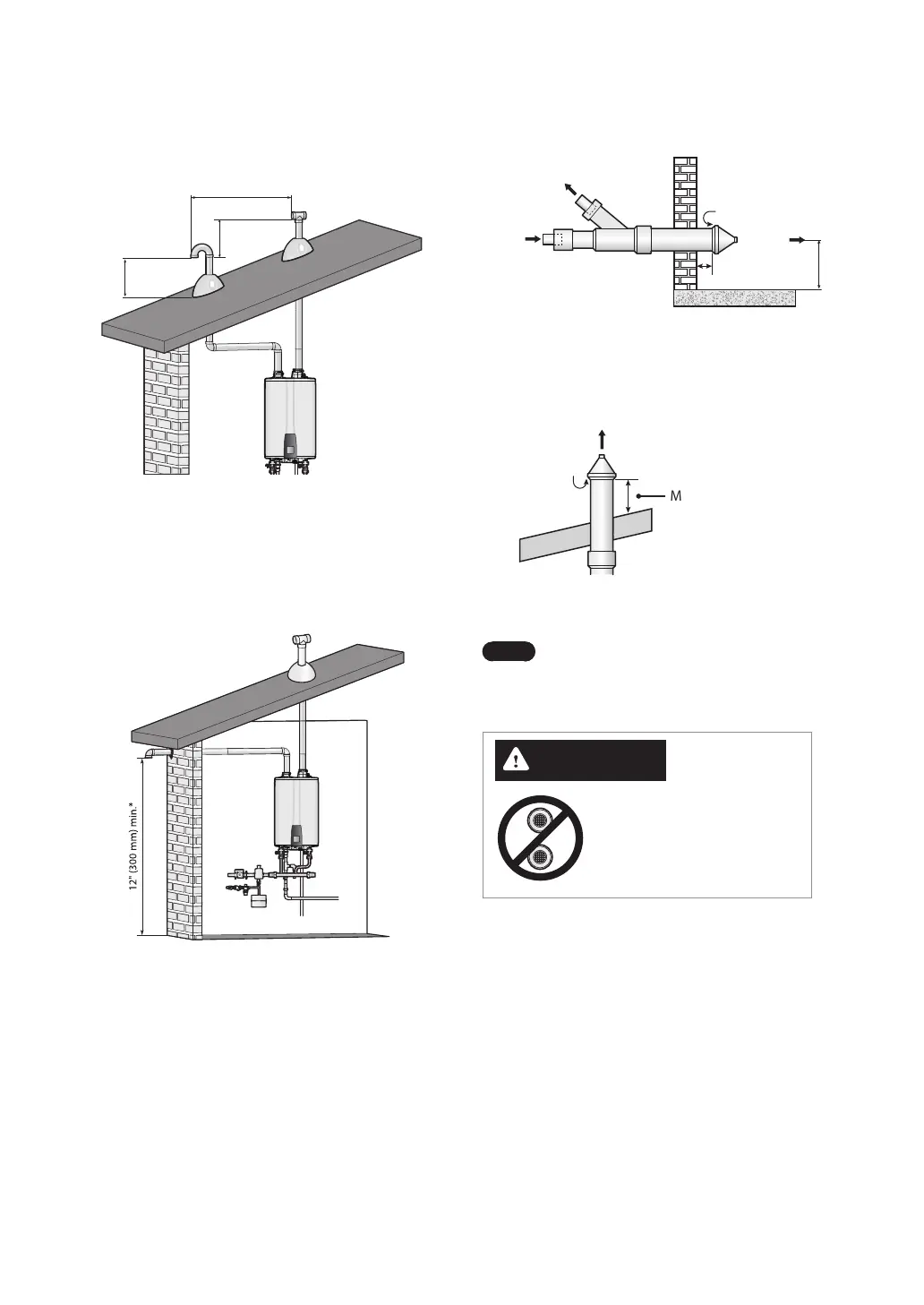
Concentric Sidewall Venting
1 in. (25 mm) min.
Combustion Air Intake
Combustion
Air Intake
Maintain 12” (300mm) min. clearance
above highest anticipated snow level or
grade, whichever is greater.
Exhaust
Gas
Exhaust
Gas
●
Concentric Vertical Venting
Maintain 12” (300 mm)
min. clearance above
highest anticipated
snow level or grade,
whichever is greater
(maximum of 24”
above roof).
Exhaust Gas
Combustion
Air Intake
Note
For cascade applications, the required
horizontal clearance between
terminations is 12” for both sidewall
and vertical venting installations.
CAUTION
Do not vertically stack concentric
terminations on sidewalls. The
circulation of exhaust gases will
cause improper operation of the
water heater.
●
Two-pipe Vertical Venting - Intake and exhaust
pipes do not have to terminate in the same area.
12” (300 mm) min
From any
obstruction
(above, below,
left, or right)
Intake Air
Exhaust Gas
12" (300 mm) min.
12" (300 mm) min.12" (300 mm) min.
36” (900 mm) min.
●
Non-Concentric Sidewall Venting: Air is drawn
from a different location that is at least 12 in. (300
mm) away from the exhaust termination. The
exhaust termination can be located either on the
sidewall or roof. Try to minimize the length of the
intake air pipe when installing the vent.
*12” (300 mm) above the highest anticipated snow
level, or as required by local codes, whichever is
greater.
 Loading...