85Installing a Common Vent System
To install a condensate drain to the Common Vent
system:
1. Form a loop with a drain hose and fix it with a
tie.
Note
●
While shaping the hose, do not
bend the hose excessively. The hose
will be deformed and the flow will
be restricted if the hose is bent in
sharp angles.
●
Do not fix the hose too tight when
tying the hose to form the loop.
The hose will be deformed and the
flow will be restricted if the tie is
too tight.
2. Prime the loop using tap water. The water inside
the hose should be higher than 7.1 in. (180 mm),
and water should be inside the hose before
operating the water heater.
3. Install the hose to the Common Vent system and
direct the end of the hose to a drain.
7.1 in.
(180 mm)
WARNING
Carbon Monoxide Hazard
Check the loop again to ensure the water is still
in the loop.
The loop (siphon) must be primed with water
before running the system to prevent toxic
exhaust gas from leaking and resulting in
serious injury or death.
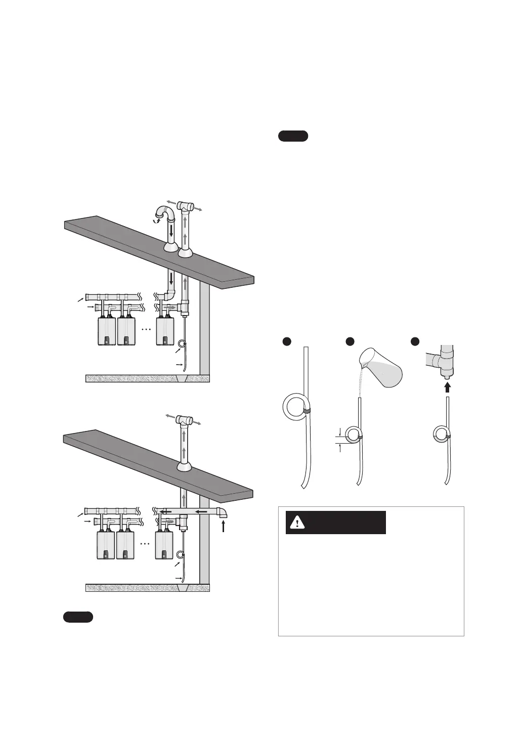
6.5 Installing a Condensate Drain
Refer to the following examples to install a
condensate drain hose (field supplied) to the
common vent system. The condensate drain hose
prevents condensate or rain from entering the
exhaust system and gathering above the Common
Vent Collar Kit. The exhaust vent must be sloped
down towards the drain to prevent water from
collecting within the pipe.
Siphon loop
Drain hose
Intake
p
Unit
12
Unit
2
Unit
1
Intake
End
Cap
Siphon loop
Drain hose
Unit
12
Unit
2
Unit
1
Note
Condensate drains may also be
placed at or near end cap in the above
example ONLY if units are connected
into the side of the header.
6.4 Connecting and Terminating the Vent Pipe
Refer to the following example to install the common vent system. The installation area should be measured to
ensure that sufficient space is available to install the water heater units and the common vent system. Ensure that
the common vent system is installed near the water heater units while satisfying all clearance requirements that
are specified in this manual as well as the Installation Manuals supplied with the water heater units.
6.4.1 Connecting the Main Pipe Runs to Wye Joint or Wye Assembly
After connecting the wye joint or wye assembly, connect the main trunk pipe to each side of the wye joint or wye
assembly. Each trunk pipe is connected to the other wye joint or wye assembly. Refer to “Connecting Pipes with
Cement” on page 76 for more information.
WARNING
Carbon Monoxide Hazard
To prevent serious injury or death:
●
ALWAYS use a bubble test kit to check for leaks.
●
After water heater is installed, fill with water, turn on the boiler and test for leaks using a bubble test kit.
●
If you see bubbles form, you will need to repair that section of pipe and bubble test again.
6.4.2 Installing the System Termination
End caps, pipe elbows or tee joints can be used at the open ends of the intake and exhaust vent pipes. Refer to the
following installation examples that depict how the parts are fitted at the end of the common vent system piping.
End Cap
Field Supplied Termination
Screen (Optional)
Note
The illustration is intended for reference purposes only.
 Loading...