7
General Purpose Input Output (GPIO):
The GPIO control allows the user to step through the Secondary image sizes as described on page 6, swap the
Primary and Secondary images or display a Record indicator in the upper left corner of the display.
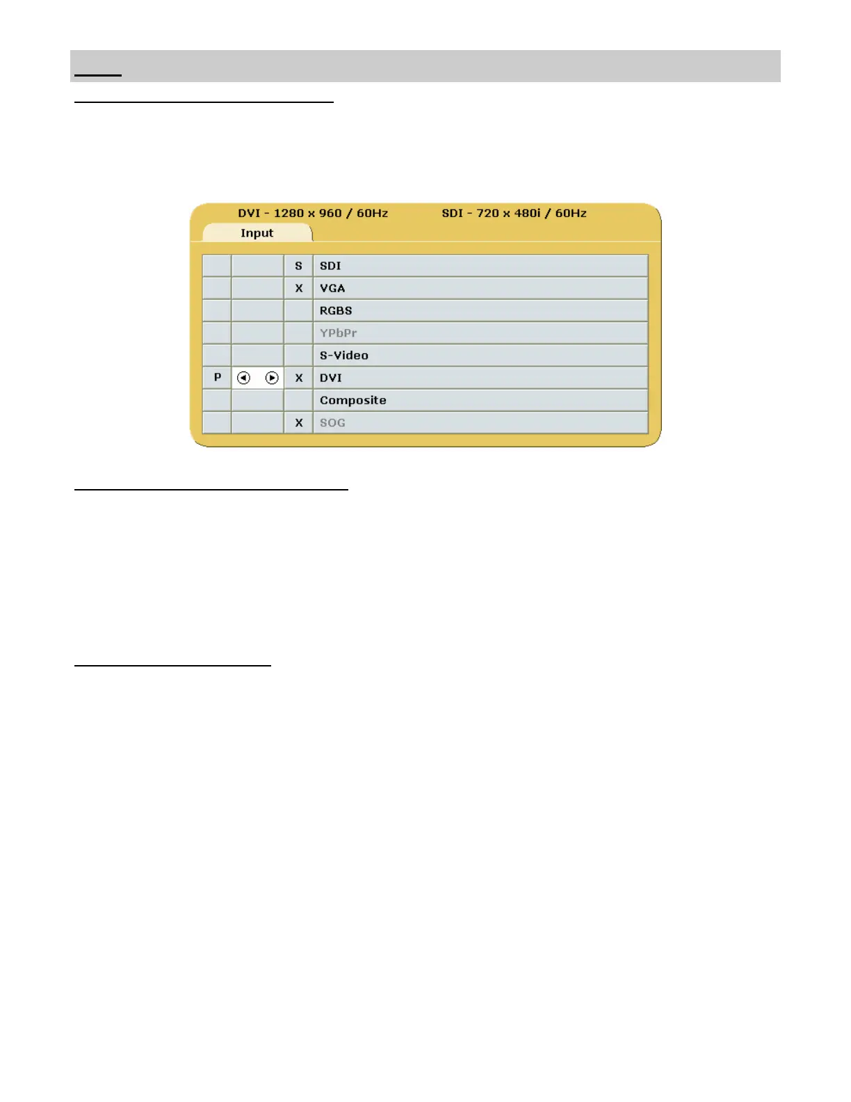
Refer to the Input Menu shown below when setting up the Primary and Secondary inputs.
GPIO
GPIO Primary / Secondary Source Setup:
1. Open the Input Menu
2. Press the SCROLL button to highlight the input that will be designated as Primary.
3. Select it by pressing the ◄ button a P in the column to the left of the cursor.
4. After the Primary input is chosen you may designate a Secondary input.
5. Press the SCROLL button to highlight the input that will be designated as Secondary.
6. Select it by pressing the ►button an S appears in the column to the right of the cursor. A small image of the
signal connected to the Secondary input appears in the upper right corner of the Primary input.
7. The Secondary input may be cleared by highlighting it using the SCROLL button and pressing the ► button.
Using GPIO Source Selection:
1. Connect an appropriately wired fixture to the GPIO connector.
2. Press the fixture’s PIP Size button.
3. The display’s Secondary image increases in size. See page 6 for the sequence.
4. Press the fixture’s Swap button. The Primary and Secondary images swap locations
5. Press the fixture’s Record button, the Record indicator is displayed until the Record button is released.
Note: GPIO connector pin out is on page 18.
 Loading...