©2018 NEC Display Solutions, Ltd. Page 12 of 71
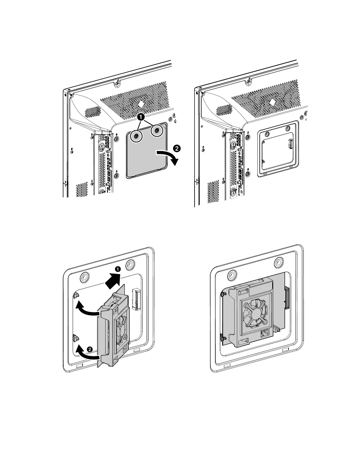
4. On the back of the display, unscrew the two screws on the interface board access cover and
remove the cover.
Figure 3.1-3: Remove the Interface Board Access Cover
5. Insert the edge connector on the interface board into the socket in the display and snap the
board into place with the two standoffs. Make sure the interface board is correctly seated.
Figure 3.1-4: Insert the Compute Module Interface Board