© by N&W GLOBAL VENDING S.p.A. 45 10 2009 3325 - 00
Chapter 3
Maintenance
The intactness of the machine and its compliance
with the rules of the relative installations shall be
checked by skilled personnel at least once a year.
Never forget to power o the machine before
performing any maintenance operation that may
require the disassembly of components.
The operations described here below may be only
performed by the personnel who have a specic
knowledge of the machine operation from the view-
point of electric safety and health rules.
GENERAL INTRODUCTION
To ensure the correct operation all over the time, the
equipment must be serviced at regular intervals.
All necessary operations and the relative deadlines are
listed here below. Obviously, they are merely indicative
since they depend upon operating conditions (e.g. water
hardness, humidity and room temperature, type of prod-
uct in use, etc.).
The operations described by this chapter are not intend-
ed to exhaust all maintenance operations.
The most complex operations (e.g. boiler descaling)
must be carried out by a technician having a specic
knowledge of the vending machine.
In order to avoid any risk of oxidation or chemical cor-
rosion in general, keep stainless steel surfaces well
cleaned and painted by using neutral detergents (please
avoid any solvent).
Under no circumstance is it allowed to use water
jets in order to wash the machine.
BREWING UNIT MAINTENANCE
The coee unit must be serviced, even if slightly, every
10,000 dispensing cycles or, any way, every 6 months to
optimise its operation all over the time.
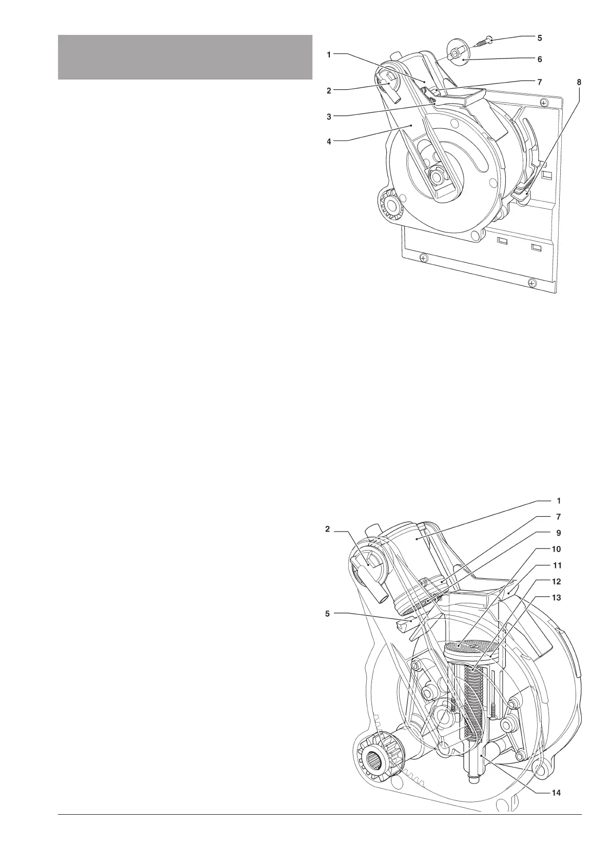
To provide for maintenance, remove the unit and act as
follows:
- Detach the coffee outlet nozzle (2) from the unit by
rotating it by 90° with respect to the connecting rod (4)
and by pulling it to the outside.
- Operate the lever (8) intended to lock the unit by rotat-
ing it to reach the horizontal position.
- Extract the coffee unit.
Fig. 30
1- Upper piston
2- Coffee outlet nozzle
3- Lower scraper
4- Connecting rod
5- Side screw
6- Key
7- Upper gasket
8- Unit locking lever
9- Upper filter
10- Lower filter
11- Lower scraper
12- Lower piston
13- Lower gasket
14- Piston rod guide
15- Upper scraper