NW Global Vending – TECHNICAL MANUAL
This document was produced by MARK AC for the exclusive use of the technical personnel in the after-sales service.
. No part of this document may be divulged to a third party or reproduced partially or entirely without the prior permission of NW GLOBAL VENDING
. All rights reserved.
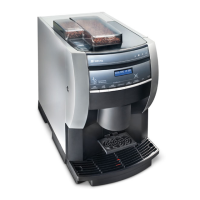
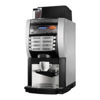
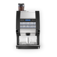
New dispenser “KORO” 07/10/2005 page 15 / 42
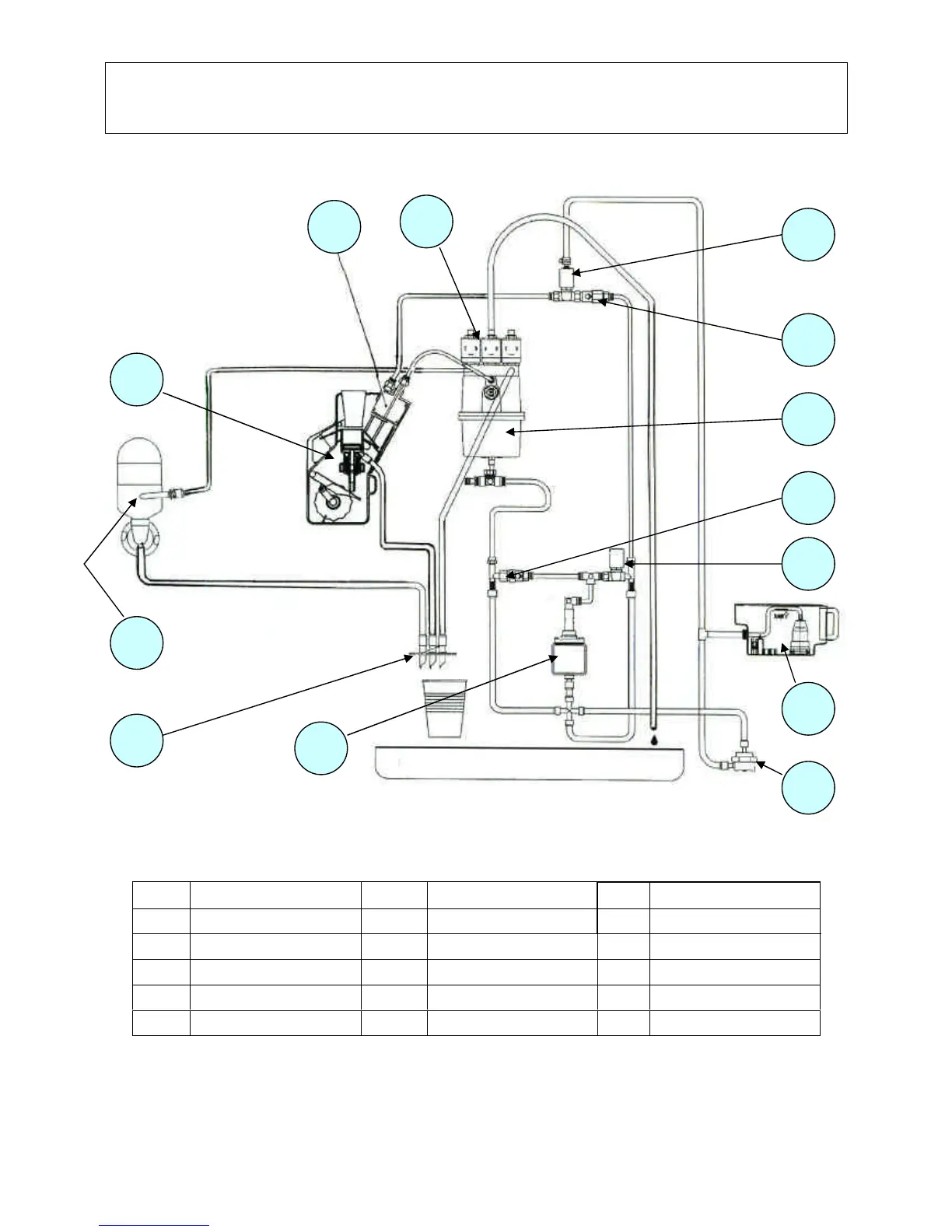
10 – HYDRAULIC LAYOUT
“VARIABLE CHAMBER ESPRESSO ”
COMPONENTS OF ESPRESSO VERSION WITH VARIABLE BREWING CHAMBER
This diagram is used exclusively for variable chamber brewer units, as it differs also with regard to the electrical circuit
and it is specific to some versions
REF. DESCRIPTION REF. DESCRIPTION REF. DESCRIPTION
1
Spouts assembly 2 Mixer unit 3 Brewer unit
4
Chamber with piston 5 Solenoid valve assembly 6 Discharge solenoid valve
7
By-pass (4 bar) 8 Boiler 9 By-pass (12 bar)
10
Piston solenoid valve 11 Water supply tank 12 Volumetric counter
13
Vibration pump