HV Control Panel
11
EN
5.4.1 Power Cable W0 Installaon into Q1
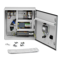
1. Removethecoverplateontheundersideofthecabinet:Savethescrewsandsealing.
2. MounttheSealingfromthecoverplateandplacethecabinetangewiththebigcable
transionstothele.Usethesavedscrewsfromcoverplatetoghtentheange
3. Pullanappropriatelysizedandapprovedcablethroughoneoftheange’slecable
seals,usetheinnerlehole.
4. Removetheprotecvecoverslocatedontheterminalsofthemainswitch.
5. PeelwiresaccordingtoTable 5-11: Cable and peeling dimensionsandmountendcaps.
6. PlacethewiresintoQ1accordingtoElectricalwiringdiagrampage50,ghtenthe
screwaccordingtoTable 5-9: Tightening Torque for Earth Bus Bar Clamp.
7. Replacetheprotecvecoveronthemainswitch.
8. TightenthePEwiresintoPEBusBarClampaccordingtoTable 5-9: Tightening Torque
for Earth Bus Bar Clamp.
9. LabelthepowercableinbothendswithsignW0.
5.4.2 Motor Cable W1 Installaon into F7
1. Pullanappropriatelysizedandapprovedcablethroughoneoftheange’slecable
seals,usetheouterlehole.
2. PeelwiresaccordingtoTable 5-11: Cable and peeling dimensionsandmountendcaps.
3. TightenthewiresintoMotorprotectorF7accordingtotheElectricalwiringdiagram.
4. TightenthescrewaccordingtoTable 5-9: Tightening Torque for Earth Bus Bar Clamp.
5. TightenthePEwiresintoPEBusBarClampaccordingtoTable 5-9: Tightening Torque
for Earth Bus Bar Clamp.
6. LabeltheMotorcableinbothendswithsignW1.
5.4.3 Motor Cable W2 Installaon into K2
1. Pullanappropriatelysizedandapprovedcablethroughoneoftheange’slecable
seals,usetheouterrighthole.
2. PeelwiresaccordingtoTable 5-11: Cable and peeling dimensionsandmountendcaps.
3. TightenthewiresintoContactorK2accordingtotheElectricalwiringdiagram.
4. TightenthescrewaccordingtoTable 5-9: Tightening Torque for Earth Bus Bar Clamp.
5. TightenthePEwiresintoPEBusBarClampaccordingtoTable 5-9: Tightening Torque
for Earth Bus Bar Clamp.
6. LabeltheMotorcableinbothendswithsignW2.
5.4.4 Installaon Maintenance Switch (MS)
InstallamaintenanceswitchnexttotheVAC/RBUiftheHVControlPanelEXisnotinthe
samelocaonorvisible,accordingtolocalregulaon.