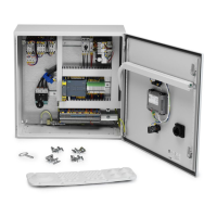
HV Control PanelEN
12
ConnectcablesaccordingtotheElectricalwiringdiagram.
1. PlaceandmounttheMSclosetoVAC/RBUUnit.
2. ConnectMotorcableW1terminal1,3,5.
3. ConnectMotorcableW3toterminal2,4,6LabelcableinbothendswithsignW3.
4. ConnectMotorcableW2terminal7,9,11.
5. ConnectMotorcableW4terminal8,10,12LabelcableinbothendswithsignW4.
6. TightenthePEwiresfromW1,W3togetherintoPEterminal.
7. TightenthePEwiresfromW2,W4togetherintoPEterminal.
8. ConnectMSSignalcableContacts13,14toterminalX1:1andterminalX1:2incontrol
cabinet.LabelSignalcableinbothendswithsignW101.
9. PullcableW126intoVAC/RBUcabinetandpullitintomotorconneconbox.
10. ConnectPTCsensorwirestoCableW126wireS1andS1.
11. LabelPTCsensorcableinbothendswithsignW126.
5.4.5 Installaon Motor Cable W3 and W4
ConnectcableaccordingtoElectricalwiringdiagram.
1. Openmotorconneconboxandidenesterminalboltsize.
2. PullcableW3intoVAC/RBUcabinetandpullitintomotorconneconbox.
3. Peelwiresandmountringcableshoeonwires.
4. TightenthewiresintoV1,U1,W1motorterminal.
5. PullcableW4intoVAC/RBUcabinetandpullitintomotorconneconbox.
6. TightenthewiresintoU2,W2,V2motorterminal.
7. TightenthePEwiresfromW3,W4togetherintoPEterminal.
5.4.6 Supplementary equipotenal
IfsupplementaryPotenalbondingisrequiredaccordingtolocalregulaons,connectitto
PEonBusbar.
5.4.7 T1 Control Transformer Voltage Sengs
NOTE! Inthesengstablesbelow,thereisacolumnforcustomerspecicsengs.See
also 17.
TransformersupplyvoltageCableismarkedwith(003).
Ifthepowersupplyisanothervoltage,forexample,230or460Volt,thetransformersupply
voltagecablemustbemovedtotheinputthatappliestothenewpowersupplyvoltage.
Whenchangingtoanotherpowersupplyvoltage,checkTable 5-12: T1 Primary Protecon
Auto Fuse F2 Seng
andadjustAutofuseF2tothenewcurrentseng.
The24VACoutputcanbeadjustedupordownbymovingthevoltagesupplycable004to
terminal-20,0V,+20V.Defaultisonterminal0V.
FillinthetablebelowaerconguraonofTransformerT1.
Table5-5:T1TransformerPrimaryInputSengandFuseF2Seng.
Alternave Seng Default (x) Parameter Customer Seng
230/(400)/460
SupplyvoltageCable(003)

 Loading...