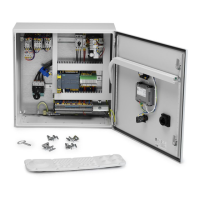
HV Control Panel
15
EN
5.4.11 Installaon of control signals
NOTE! Intheelectricaldiagram,notewhichexternalcomponentsareconnectedtothe
cabinet.
NOTE! RememberthatforinstallaonsinanEXenvironment,alwaysfollowlocal
regulaonsandthestandards.Seealsosecon3. Safety.
Acontrolsignalhasavoltagerangeof0-30VAC/DC,anditismainlyconnectedtoterminal
X1:1->X1:xx.Itscomponentsareoutsideofthecabinet.
SizeandcolourofcontrolsignalwireisstatedinElectricalwiringdiagrampage7-8.
TheconnectedobjectssuchassolenoidvalveorsensorshavetobeapprovedfortheEX
zonetheyinstalledin.Anintrinsicallysafecircuitmaybeneeded.Seealsosecon3. Safety.
Beawarethat0VAC/DCsupplyisconnectedtoground,sowiressupplyingsensorsand
solenoidswillshortcircuitthe24Vsupplyifitconnectstoground,andcausefusesF4orF5
tointerrupt.
TerminalX1isformaximum2,5mm
2
wires,butusing0,75mm
2
wirecombinedwithanend
capisrecommended.
5.4.12 To do before Power up Control Cabinet
Checkthefollowing:
1. ThemotorandcontrolcabinetisinstalledaccordingtoElectricalInstallaon
Instrucons.
2. Thecontrolcabinetisproperlygrounded.
3. Theinputpower(Mains)voltagematchestheT1Transformerinputvoltagesengs.
4. Theinputpower(Mains)voltageisconnectedtoMainswitchQ1terminalsandis
ghtenedasspeciedinTable 5-10: Tightening Torque for Cable Connecon.
5. ThemotorcableW1isconnectedtomotorprotectorandF7isghtenedasspecied
inTable 5-10: Tightening Torque for Cable Connecon.
6. ThemotorcableW2isconnectedtocontactorF7andisghtenedasspeciedinTable
5-10: Tightening Torque for Cable Connecon.
7. ThemotorcableW3-W4iscorrectlyconnectedtomotorterminalsandghtened.
8. VerifythatcontrolcablesW101->WXXarelabelledandconnectedtocorrect
terminalsaccordingtotheElectricalwiringdiagram.
9. PerformaPEConnuoustest-ontoensurethePEwiresarecorrectlyconnected.
10. Visuallyinspectandcleanupcabinetfromforeignobjectssuchas,drillshavings,nuts
bolts,cable/wiringpeelingresidualsetc.
5.4.13 Power up Control Cabinet
Itispreferabletopowerupthecabinetbeforeanycontrolcableisconnectedexceptthe
PTCandMaintenanceSwitchcontrolcable.Thenitispossibletotestthe24VAC/DCsupply
outputwithoutanyaccidentalshortcircuitsfromcontrolcables.
Beforepoweringupthecabinet,checkallpowerconneconsandcheckthatControl
transformerT1isconnectedtosamevoltageascabinetpowervoltagesupply.
Beforeturningonthevoltage,alwaysmeasuretheincomingvoltagetoverifythatthe
cabinet’scontroltransformergetsthecorrectvoltage.
MainsvoltageisaccessibleformeasurementonQ1incomingterminals.