Figures
2
3
4
6
11
15
15
16
17
17
18
18
19
20
33
38
38
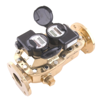
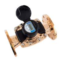
Figure 1 – 3-Inch Commercial and Industrial MACH 10
®
Ultrasonic Meter
Figure 2 – Cross-Section of a 3-Inch Commercial and Industrial MACH 10
®
Figure 3 – Unitized Measuring Element
Figure 4 – Commercial and Industrial Meter Dimensions – Side View
Figure 5 – Bleed Screw Location
Figure 6 – Scotchlok™ Connector
Figure 7 – Seat the Connector Wires
Figure 8 – Crimping Tool
Figure 9 – Three Colored Wires Connected
Figure 10 – Splice Tube
Figure 11 – Gray Wires in Slot
Figure 12 – Cover in Place
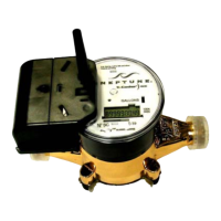
Figure 13 – Commercial and Industrial MACH 10
®
Meter
Figure 14 – MACH 10
®
LCD Panel
Figure 15 – Unitized Measuring Element Commercial and Industrial MACH 10
®
Meter
Figure 16 – Commercial and Industrial MACH10
®
)R900i™ – Top View
Figure 17 – Commercial and Industrial MACH 10
®
)R900i™ – Front View
Figure 18 – Commercial and Industrial Meter Dimensions – End View
39
Commercial and Industrial MACH 10
®
Ultrasonic Meter Installation and Maintenance Guide ix
 Loading...