Saturn Bt – Chapter 1. Getting Started1.12
Connecting Up Cont’d
5 4 3 2 1
9 8 7 6
25 24 23 22 21 20 19 18 17 16 15 14
13 12 11 10 9 8 7 6 5 4 3 2 1
1 2 3 4 5
6 7 8 9
5 4 3 2 1
9 8 7 6
OFF
+ [11 - 34 VDC] -
ON
HANDSET
EXT I/O GYRO
NMEA-0183
DTE
TEL.1 TEL.2 TEL.3 TEL.4 TEL.5
AUX
PC PRINTER
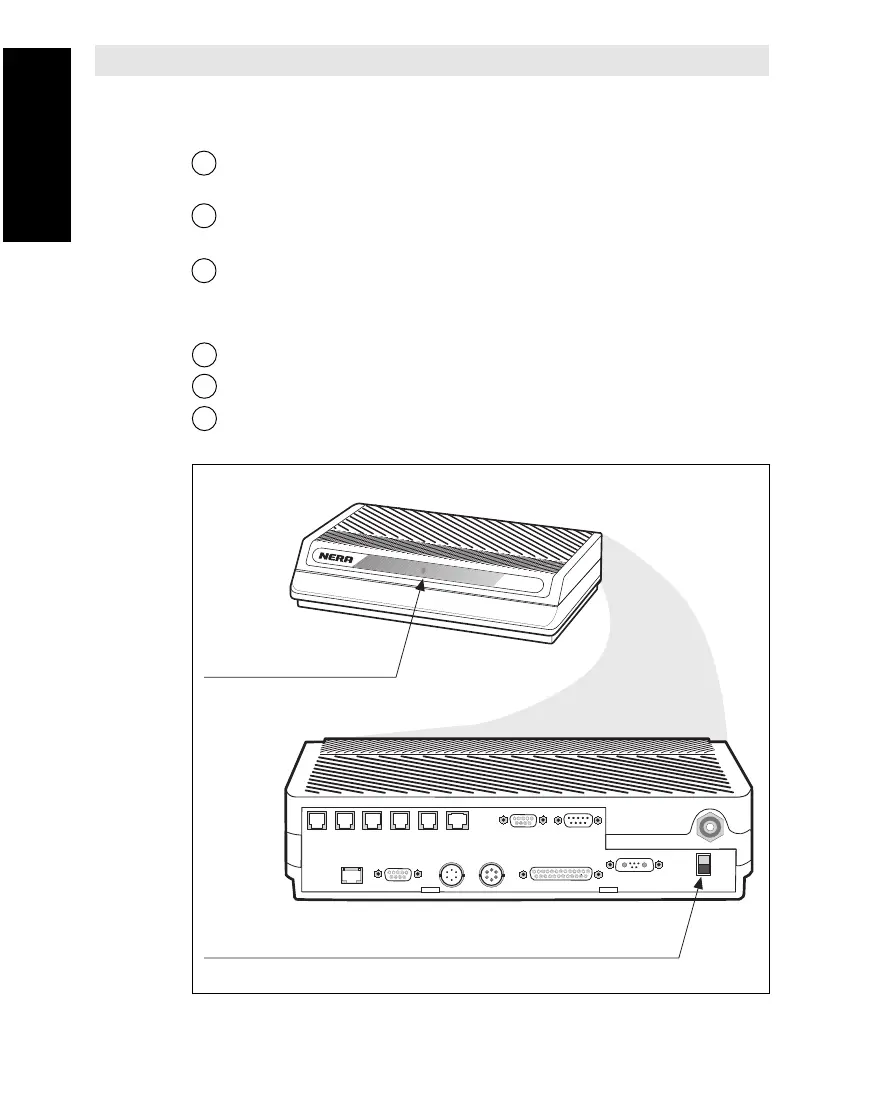
Power ON/OFF
Power indicator
Saturn B
Connector Up Cont’d
Figure 1.4 Location of Power Indicator and ON/OFF switch on Main Control Unit.
Procedure
See Connecting Up diagram on previous page.
1 Connect coax cable between Antenna Feeder (underneath dish)
and Transceiver (top side)
2 Connect coax cable between Transceiver (underneath) and Main
Control Unit (MCU).
3 Connect appropriate equipment as shown on figure on diagram.
Power
4 Connect Saturn Bt to an appropriate AC (or DC) source.
5
Switch ON External Power Supply and wait for approx. 2 seconds
.
6 Press the POWER switch (see below) and permit the equipment
to warm up.