C-1Saturn B – Chapter 5. Appendices
Connection of
Message Indicator
12345
12345
12345
12345
TB1 TB2
2
6
9
5
1414
TB1
OPEN
OPEN
OPEN
OPEN
To MCU
EXT I/O
(J10)
EXT-A
EXT-B
12V FUSED
Message
Indicator
+12V
EXT I/O
CONNECTOR J10
To TB1 on next
Message Indicator
(if used)
To TB1 on next
Message Indicator
Message Indicator
N
SATURN B
D
A
T
A
M
E
S
S
A
G
E
T
E
L
E
X
M
E
S
S
A
G
E
F
A
X
M
E
S
S
A
G
E
R
E
S
E
T
5 4 3 2 1
9 8 7 6
(J10)
EXT I/O
TB1 TB2
Setting 1
Switches 1 and 4
are set to OPEN
Side view of
switch 1
OPEN
Setting 2
Switches 2 and 4
are set to OPEN
Setting 3
Switches 1, 2 and 4
are set to OPEN
Setting 4
Switches 3 and 4
are set to OPEN
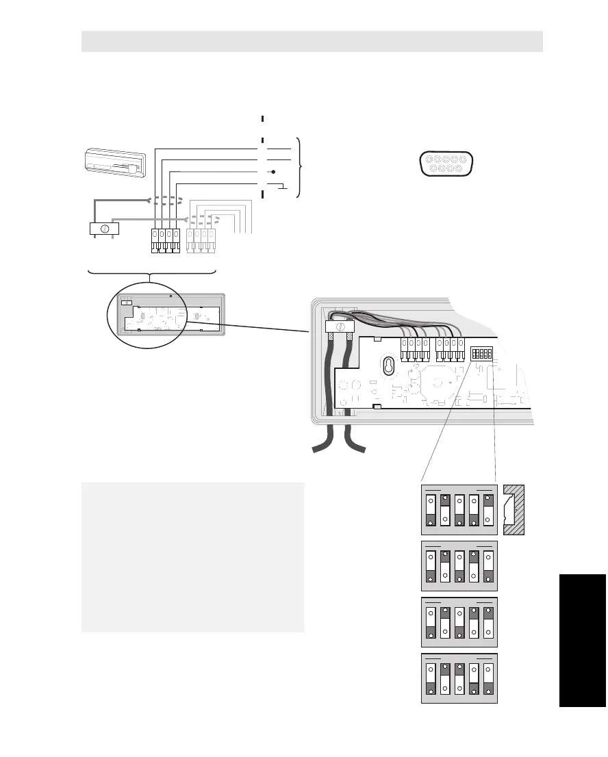
Each Message Indicator must have
its own separate switch setting.
The setting is done with the DIP
switch inside the Message Indicator
according to the figure.
For programming of the MCU, see
"Various Configurations" in chapter
3. Configuration.
Appendix C – Connection of Message Indicator
The Message Indicators (max. 4) are connected to the EXT I/O (J10) outlet
located on the rear panel of the MCU. See diagram for pin configuration.
Appendix C
Connection of Message Indicator