LIB-4400/4424 Installation Guide
| MANUAL Page 19 of 65
Ship Kit Contents
The LIB-4xxx is shipped with several standard components. Make sure you have received the
following:
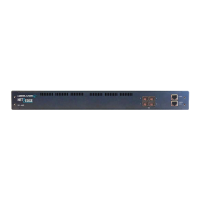
• One LIB-4400 NID or one /LIB-4424 switch
• One CONSOLE Cable, DB9 Fem-to-RJ45 Male, 6Ft. (TN PN 27232) (CISCO 72-3383-01)
• One printed Product Documentation postcard
• Rubber feet
• One cardboard insert
• Two foam endcaps
Other / Optional Items
Additional items used during installation may include one or more SFPs, SGMII device(s), a USB
cable, Ethernet CAT 6 or CAT 6E cable(s) and/or Fiber cable(s), and rack mount brackets.
Tools Required
Installation may require a #4 Phillips screwdriver.
Additional tools and equipment required for cleaning connectors may include dust caps, isopropyl
alcohol (solvent for contaminants), and tissues (soft multi-layered fabric made from non-recycled
cellulose).
Use industry standard procedures for cleaning connectors. If applicable, follow your organizations
process and procedure for copper and fiber cable cleaning and maintenance.
Installation Overview
o Review the Safety section above (see 2.1 Safety on page 18).
o Unpack the LIB-4xxx (see 2.2 Unpacking on page 18).
o Perform desktop install (see Desktop / Tabletop Installation on page 24) or
perform rack mount install procedure (see Rack Mount Installation on page 24).
o Connect PORT 1 - PORT 4 (see Front Panel Connectors and LEDs on page 20).
o Install SFPs (see Installing SFPs on page 25).
o Connect the MGMT port to a PC’s Ethernet NIC port.
o Connect the CONSOLE PORT (see Front Panel Connectors and LEDs on page 20).
o Perform grounding (see Grounding the LIB-4xxx (Rack Mount) on page 29).
o Install the Power Suppy (ies) (see “
Installing the DC Power Supply” on page 27
or “
Installing the AC Power Supply” on page 28).
o Connect Power (see “Connecting to the DC Power Supply” on page 29 or “Connecting to the DC
Power Supply” on page 31).
o Monitor the LEDs (see Front Panel Connectors and LEDs on page 20).
o Install the Software (see Software Install Process on page 32).
 Loading...