LIB-4400/4424 Installation Guide
| MANUAL Page 20 of 65
If the install was successful, continue with the related Web User Guide or CLI Reference manual.
If the install was unsuccessful, refer to the Troubleshooting section in the online Web User Guide.
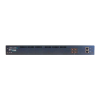
Front Panel Connectors and LEDs
The LIB-4400 front panel connectors and LEDs are shown and described below:
Figure 4a: LIB-4400 Front Panel Connectors and LEDs
Front Panel
1. Power input for Power Supply 1.
2. Fan for Power Supply 1.
3. Power input for Power Supply 2.
4. Fan for Power Supply 2.
5. LEDs P1 - P4: One LED per port, bi-color (Green/Yellow)
Green = ON green when linked at 10GE, OFF when not linked, BLINK when activity.
Yellow = ON yellow when linked at 1GE, OFF when not linked, BLINK when activity.
When first connected, the Port 1-4 LEDS turn yellow while a link is established. After
about 15 seconds, the LED turns green when the LIB-4400 and the target device have
established a fibre link. If this LED remains off after cable is connected, check 1) remote power, 2)
cabling, and 3) interface modes of both the local and remote devices (speed, duplex, auto
negotiation, etc. See the Troubleshooting section of the related online User Guide manual for more
information.
6. PORT 1 - PORT 4: Four Ethernet 10 GE SFP+ ports.
The LIB-4400 supports 1Gbps, but the behaviour is
different than a normal 1G SFP port (no SFP detect).
7. PWR (Power) LED: Green ON = power on to device;
Primary Green
Secondary Green
 Loading...