LIB-4400/4424 Installation Guide
| MANUAL Page 21 of 65
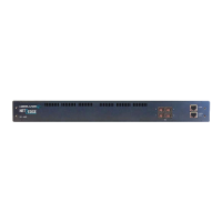
8. S1 LED (System Status LED) and S2 LED - Power Source LED.
S1 - System Status LED. During normal boot up this LED will be amber.
Once the device is fully booted it will turn green.
During firmware upgrade this LED will flash green.
When a fatal condition is logged, S1 flashes amber.
9. USB port (not currently programmed to recognize USB devices).
10. CONSOLE Port: One Ethernet RJ-45 female connector for connection to a computer
for console control / administration (shown below). The CONSOLE port can be used for
accessing the LIB-4xxx CLI for out-of-band management. The COM port can be
connected at 115k baud with 8/N/1/None connection setting. See the “Software Install
Process” on page 32 for more information.
11. MGMT 10/100/1000 Port: One Ethernet RJ-45 connection for out-of-band management over the
IP network the RJ-45 port is provided to keep management traffic totally isolated from data traffic.
Connect the MGMT port to a PC’s Ethernet NIC port to use this management function.
11. MGMT port LED:
Left LED: ON=Link, BLINK=Activity, Green=Full duplex, Yellow=Half duplex
Right LED: When linked, Green=1G Yellow=100M OFF=10M
2. IEEE 1588 OUT: SMB connection for Sync-E timing output 1 to 25 KHz (2.0V into 50 ohm, 4V into
High-Z.
13. IEEE 1588 IN: SMB connection for Sync-E timing input (TTL, minimum 100ns high pulse, 50-75-
High-Z termination). Input: 1 PPS, 8 KHz, 64 KHz, 1.544 MHz, 2.048 MHz, 10 MHz, 19.44 MHz, and
25 MHz.
14. Sync-E Out: SMB connection for PTP timing output. Sync-E interfaces (2 KHz to
25 MHz; 1500VAC isolated. SMB coaxial OUTPUT: 2.0V into 50 ohm, 4V into High-Z.
15. Sync-E In: SMB connection for PTP timing input. SMB coaxial INPUT: 1Vpp to
5Vpp, Sine or square wave, minimum 40/60 duty cycle, 50-75-High-Z termination. IN:
8 KHz, 64 KHz, 1.544 MHz, 2.048 MHz, 10 MHz, 19.44 MHz and 25 MHz.
1500VAC isolated.
 Loading...