LIB-4400/4424 Installation Guide
| MANUAL Page 22 of 65
16. IEEE 1588 PTP LED:
Off = Input Disabled;
Flashing Amber = No signal detected;
Yellow = Signal detected, but incorrect frequency or unstable.
Flashing Green -- N/A;
Green = Valid signal detected.
17. SYNC-E LED:
Off = Disabled;
Flashing Amber = No signal detected;
Yellow = Signal detected, but incorrect frequency or unstable.
Flashing Green = Locked;
Green = Selected, and using as primary clock source.
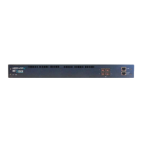
The front panel connectors and LEDs are shown and described below:
Figure 4b: Front Panel
P1-P12 LEDs
Two LEDs for each port, one Green and one Yellow:
Green LED = ON when linked, OFF when not linked, BLINK when activity.
Yellow LED = Indicates speed when linked, ON=1GE, OFF=100FX.
P13-P14 LEDs
Two LEDs for each port, one Green and one Yellow:
Green LED = ON when linked, OFF when not linked, BLINK when activity.
Yellow LED = Indicates speed when linked, ON=10GE, OFF=1GE.
 Loading...