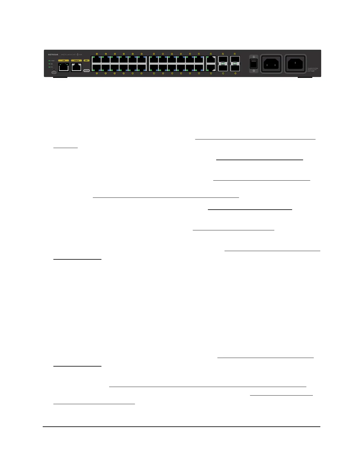
Figure 12. Back panel model M4250-26G4F-PoE++
From left to right, the back panel of models M4250-26G4F-PoE+, M4250-26G4XF-PoE+,
and M4250-26G4F-PoE++ provides the following common components, which are
clearly named or numbered on the back panel:
•
POWER, FAN, and POE: System LEDs (see LEDs of the 24-port PoE+ and PoE++
models on page 21).
•
RESET: Recessed dual-function Reset button (see Dual-function Reset button on
page 36).
•
OOB: One out-of-band (OOB) Ethernet port (see Out-of-band 1G Ethernet port on
page 37) with a left LED that indicates the speed and a right LED that indicates the
activity (see LEDs of the 24-port PoE+ and PoE++ models on page 21).
•
CONSOLE: One RJ-45 RS-232 console port (see RJ-45 RS-232 console port on page
37).
•
USB C: One USB Type-C console port (see USB Type-C console port on page 38).
•
Ports 1 through 24: Eight PoE+ or PoE++ 10/100/1000 Mbps autosensing 1GBASE-T
RJ-45 ports, each with a left LED and a right LED (see LEDs of the 24-port PoE+ and
PoE++ models on page 21).
The type of PoE power and PoE budget depend on the model:
- Model M4250-26G4F-PoE+: 24 PoE+ (802.3at) ports with a total PoE budget
of 300W for the switch.
- Model M4250-26G4XF-PoE+: 24 PoE+ (802.3at) ports with a total PoE budget
of 480W for the switch.
- Model M4250-26G4F-PoE++: 24 PoE++ (802.3bt) ports with a total PoE budget
of 1440W (with both internal power supply units connected) for the switch.
•
Ports 25 and 26: Two 10/100/1000 Mbps autosensing 1GBASE-T RJ-45 ports s,
each with a combined speed and activity LED (see LEDs of the 24-port PoE+ and
PoE++ models on page 21).
•
Ports 27, 28, 29, and 30: Four dedicated 1GBASE-X SFP or 10GBASE-X SFP+ fiber
uplink ports (see Transceiver modules and cables for SFP and SFP+ fiber ports on
page 35), each with a combined speed and activity LED (see LEDs of the 24-port
PoE+ and PoE++ models on page 21).
Hardware Installation Guide20Hardware Overview
AV Line of Fully Managed Switches M4250 Series
 Loading...