NB3700 User Manual 3.8
4.3. Installation of the SIM Card
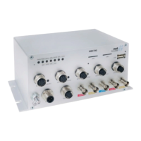
SIM cards can be inserted by sliding it into one of the designated holes on the front
panel. Insert any SIM card with the sloped corner towards the device and the contacts
towards to bottom side. By using a small paper clip (or similar) you will need to press
it a bit until it snaps into place. For removing the SIM, you will need to push it again
in the same manner. The SIM card will then rebounce and can be pulled out.
SIMs can be assigned flexibly to any modem in the system. It is also possible to switch
a SIM to a different modem during operation, for instance if you want to use another
provider upon a certain condition. However, a SIM switch usually takes about 10-20
seconds which can be bypassed (e.g. at bootup) if SIMs are installed reasonably. Using
only a single SIM with one modem, it should be preferably placed into the SIM 1 holder.
For systems which should operate two modems with two SIMs in parallel, we recommend
to assign Mobile 1 to SIM 1 and Mobile 2 to SIM 2.
Further information about SIM configuration can be found in chapter 5.3.3.
4.4. Installation of the WLAN Antennas
Any WLAN antennas must be mounted to the connectors WLAN1 and WLAN2. The
number of attached antennas can be configured in the software. If only one antenna is
used, it must be attached to WLAN1. However, for better diversity and thus better
throughput and coverage, we highly recommend using two antennas.
4.5. Installation of the Local Area Network
Up to two 10/100 Mbps Ethernet devices can be directly connected to the router, fur-
ther devices can be attached via an addtional Ethernet switch. Please ensure that the
connector has been plugged in properly and remains in a fixed state, you might other-
wise experience sporadical link loss during operation. The Link/Act LED will lit up as
soon as the device has synced. If not, it might be necessary to configure a different link
setting as described in chapter 5.3.2.
4.6. Installation of the Power Supply
The router can be powered with an external source supplying between 12 VDC and 48 VDC
or 50 VDC and 136 VDC respectively. It is to be used with a certified (CE or equivalent)
power supply, which must have a limited and SELV circuit output. The router is now
ready for getting engaged.
22