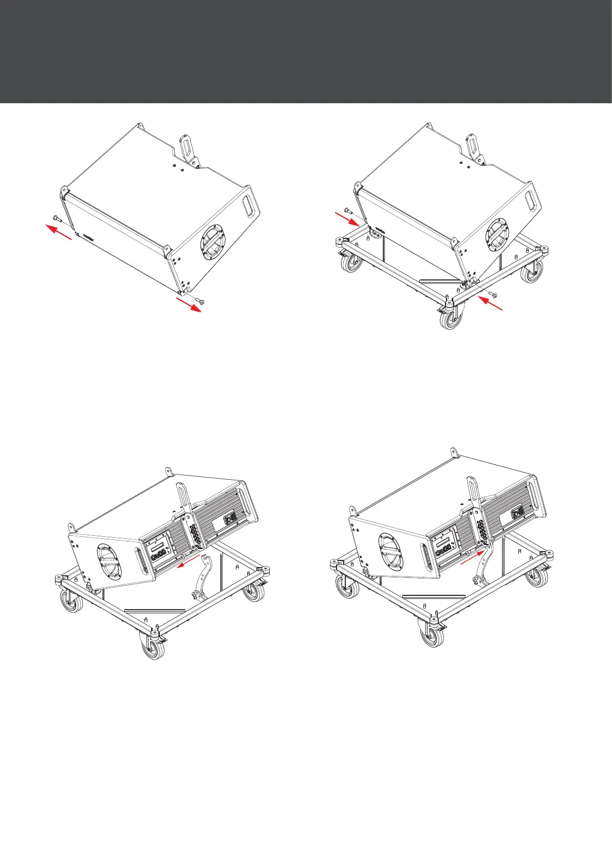
31
Step 5:
Remove the pins for the bottom of
the front rigging assemblies of the
rst cabinet to be added to the
dolly.
Step 6:
Lower the cabinet into position as
shown and insert the pins to x it to
the dolly.
Step 7:
Remove the pin for the left hand
side of the rear rigging assembly
with the right hand pin in hole
number 1 (labelled transport dolly
pin).
Step 8:
Lower the cabinet onto the rear link
and insert the pin on the left hand
side of the rear rigging assembly in
the hole marked transport dolly pin.
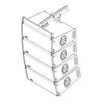
4 Mechanical Congurations