https://reference.digilentinc.com/reference/programmable-logic/nexys-a7/reference-manual 12/30
Xilinx offers the Clocking Wizard IP core to help users generate the different clocks required for a specific design. This wizard will properly
instantiate the needed MMCMs and PLLs based on the desired frequencies and phase relationships specified by the user. The wizard will
then output an easy-to-use wrapper component around these clocking resources that can be inserted into the user’s design. The clocking
wizard can be accessed from within the Project Navigator or Core Generator tools.
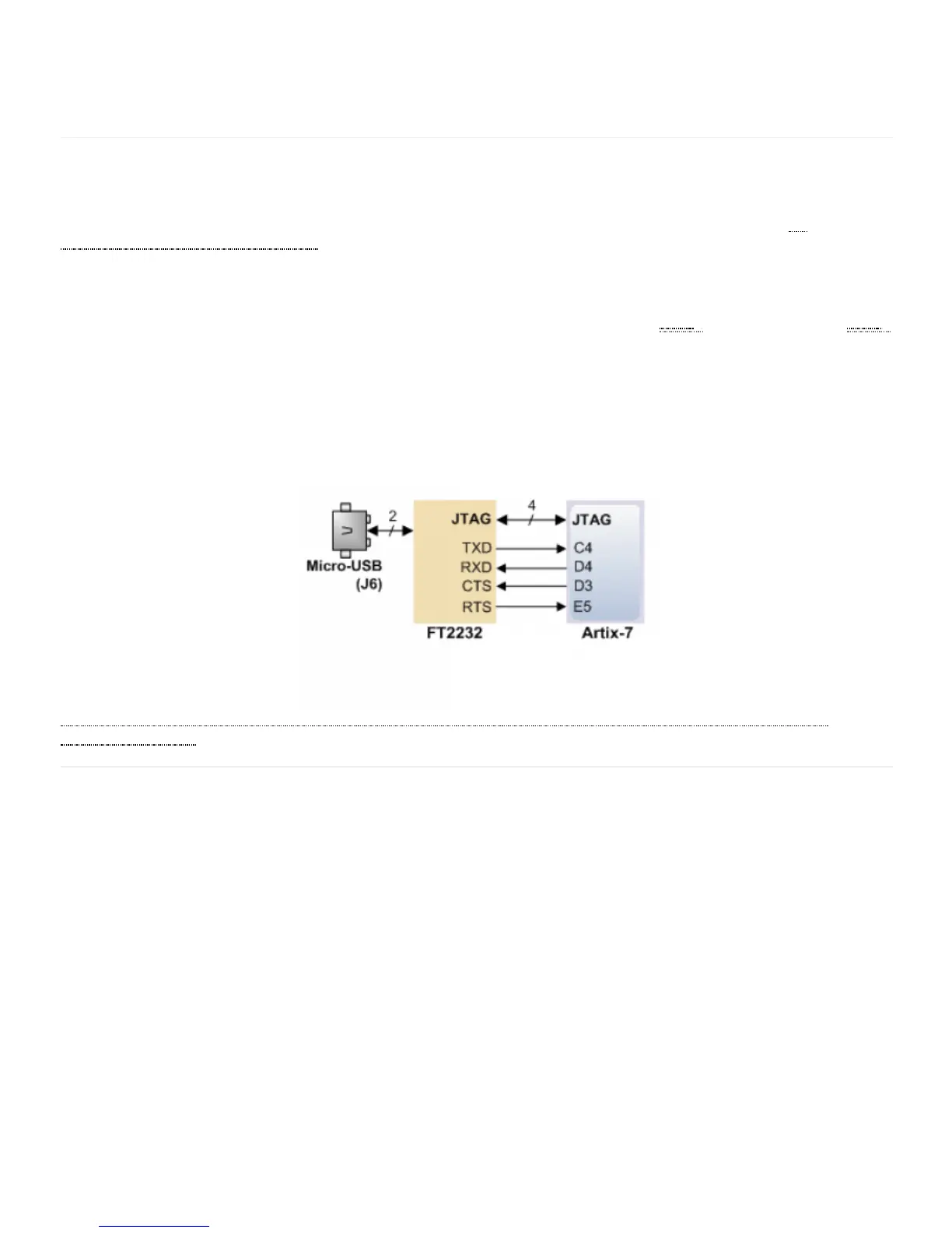
The Nexys A7 includes an FTDI FT2232HQ USB-UART bridge (attached to connector J6) that allows you use PC applications to
communicate with the board using standard Windows COM port commands. Free USB-COM port drivers, available from
www.ftdichip.com (http://www.ftdichip.com) under the “Virtual Com Port” or VCP heading, convert USB packets to UART/serial port data.
Serial port data is exchanged with the FPGA using a two-wire serial port (TXD/RXD) and optional hardware flow control (RTS/CTS).
After the drivers are installed, I/O commands can be used from the PC directed to the COM port to produce serial data traffic on the C4
and D4 FPGA pins.
Two on-board status LEDs provide visual feedback on traffic flowing through the port: the transmit LED () (LD20) and the receive LED ()
(LD19). Signal names that imply direction are from the point-of-view of the DTE (Data Terminal Equipment), in this case the PC.
The FT2232HQ is also used as the controller for the Digilent USB-JTAG circuitry, but the USB-UART and USB-JTAG functions behave
entirely independent of one another. Programmers interested in using the UART functionality of the FT2232 within their design do not
need to worry about the JTAG circuitry interfering with the UART data transfers, and vice-versa. The combination of these two features
into a single device allows the Nexys A7 to be programmed, communicated with via UART, and powered from a computer attached with a
single Micro USB cable.
The connections between the FT2232HQ and the Artix-7 are shown in Figure 6.1.
(https://reference.digilentinc.com/_detail/reference/programmable-logic/nexys-a7/n4h.png?id=reference%3Aprogrammable-logic%3Anexys-
a7%3Areference-manual) Figure 6.1 Nexys A7 FT2322HQ Connections
The Auxiliary Function microcontroller (Microchip PIC24FJ128) provides the Nexys A7 with USB Embedded HID host capability. After
power-up, the microcontroller is in configuration mode, either downloading a bitstream to the FPGA, or waiting to be programmed from
other sources. Once the FPGA is programmed, the microcontroller switches to application mode, which is USB HID Host in this case.
Firmware in the microcontroller can drive a mouse or a keyboard attached to the type A USB connector at J5 labeled “USB Host”. Hub
support is not currently available, so only a single mouse or a single keyboard can be used. Only keyboards and mice supporting the Boot
HID interface are supported. The PIC24 drives several signals into the FPGA – two are used to implement a standard PS/2 interface for
communication with a mouse or keyboard, and the others are connected to the FPGA’s two-wire serial programming port, so the FPGA
can be programmed from a file stored on a USB pen drive or microSD card.
6 USB-UART Bridge (Serial Port)
7 USB HID Host
 Loading...