https://reference.digilentinc.com/reference/programmable-logic/nexys-a7/reference-manual 20/30
(https://reference.digilentinc.com/_detail/reference/programmable-logic/nexys-a7/n4r.png?id=reference%3Aprogrammable-logic%3Anexys-
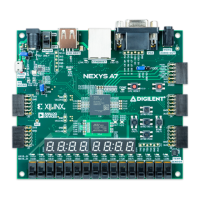
a7%3Areference-manual) Figure 9.1 General Purpose I/O Devices on the Nexys A7
The sixteen individual high-efficiency LEDs are anode-connected to the FPGA via 330-ohm resistors, so they will turn on when a logic high
voltage is applied to their respective I/O pin. Additional LEDs that are not user-accessible indicate power-on, FPGA programming status,
and USB and Ethernet port status.
The Nexys A7 board contains two four-digit common anode seven-segment LED () displays, configured to behave like a single eight-digit
display. Each of the eight digits is composed of seven segments arranged in a “figure 8” pattern, with an LED () embedded in each segment.
Segment LEDs can be individually illuminated, so any one of 128 patterns can be displayed on a digit by illuminating certain LED ()
segments and leaving the others dark, as shown in Figure 9.1.1. Of these 128 possible patterns, the ten corresponding to the decimal digits
are the most useful.
9.1 Seven-Segment Display