https://reference.digilentinc.com/reference/programmable-logic/nexys-a7/reference-manual 13/30
(https://reference.digilentinc.com/_detail/reference/programmable-logic/nexys-a7/n4i.png?id=reference%3Aprogrammable-logic%3Anexys-
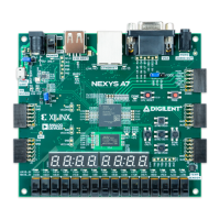
a7%3Areference-manual) Figure 7.1 Nexys A7 PIC24 Connections
The Auxiliary Function microcontroller hides the USB HID protocol from the FPGA and emulates an old-style PS/2 bus. The
microcontroller behaves just like a PS/2 keyboard or mouse would. This means new designs can re-use existing PS/2 IP cores. Mice and
keyboards that use the PS/2 protocol use a two-wire serial bus (clock and data) to communicate with a host. On the Nexys A7, the
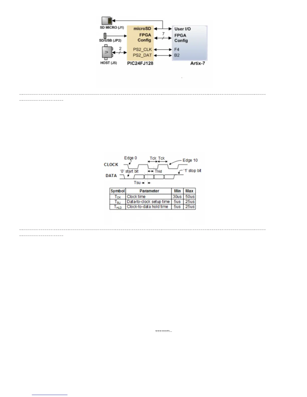
microcontroller emulates a PS/2 device while the FPGA plays the role of the host. Both the mouse and the keyboard use 11-bit words that
include a start bit, data byte (LSB first), odd parity, and stop bit, but the data packets are organized differently, and the keyboard interface
allows bi-directional data transfers (so the host device can illuminate state LEDs on the keyboard). Bus timings are shown in Figure 7.1.1.
(https://reference.digilentinc.com/_detail/reference/programmable-logic/nexys-a7/n4j.png?id=reference%3Aprogrammable-logic%3Anexys-
a7%3Areference-manual) Figure 7.1.1 PS/2 Device-to-Host Timing Diagram
The clock and data signals are only driven when data transfers occur; otherwise, they are held in the idle state at high-impedance (open-drain
drivers). This requires that when the PS/2 signals are used in a design, internal pull-ups must be enabled in the FPGA on the data and clock
pins. The clock signal is normally driven by the device, but may be held low by the host in special cases. The timings define signal
requirements for mouse-to-host communications and bi-directional keyboard communications. A PS/2 interface circuit can be implemented
in the FPGA to create a keyboard or mouse interface.
When a keyboard or mouse is connected to the Nexys A7, a “self-test passed” command (0xAA) is sent to the host. After this, commands
may be issued to the device. Since both the keyboard and the mouse use the same PS/2 port, one can tell the type of device connected using
the device ID. This ID can be read by issuing a Read ID command (0xF2). Also, a mouse sends its ID (0x00) right after the “self-test
passed” command, which distinguishes it from a keyboard.
PS/2-style keyboards use scan codes to communicate key press data. Each key is assigned a code that is sent whenever the key is pressed. If
the key is held down, the scan code will be sent repeatedly about once every 100ms. When a key is released, an F0 key-up code is sent,
followed by the scan code of the released key. If a key can be shifted to produce a new character (like a capital letter), then a shift character
is sent in addition to the scan code and the host must determine which ASCII () character to use. Some keys, called extended keys, send an
E0 ahead of the scan code (and they may send more than one scan code). When an extended key is released, an E0 F0 key-up code is sent,
followed by the scan code. Scan codes for most keys are shown in Figure 7.2.1.
7.1 HID Controller
7.2 Keyboard
 Loading...