https://reference.digilentinc.com/reference/programmable-logic/nexys-a7/reference-manual 28/30
(https://reference.digilentinc.com/_detail/reference/programmable-logic/nexys-a7/n4af.png?id=reference%3Aprogrammable-logic%3Anexys-
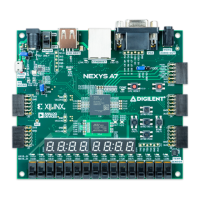
a7%3Areference-manual) Figure 15.2 SK Butterworth Low-Pass Filter Frequency Response
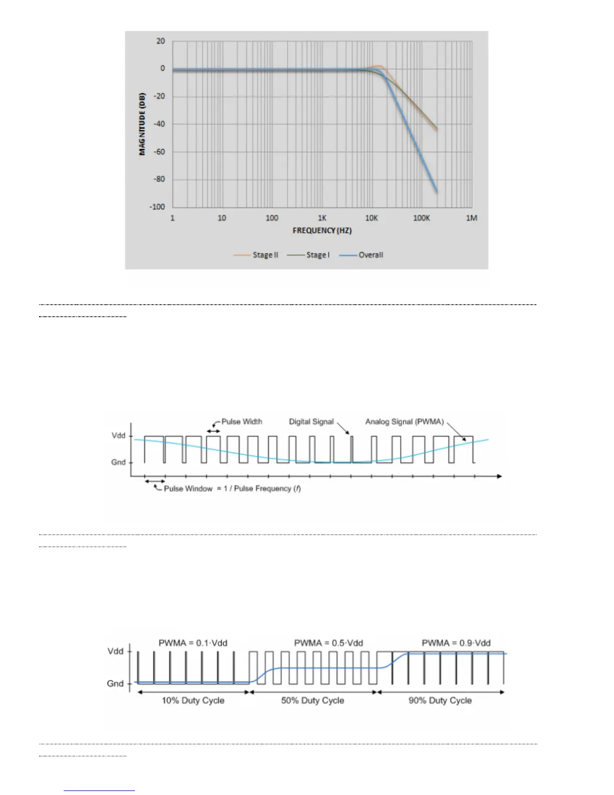
A pulse-width modulated (PWM) signal is a chain of pulses at some fixed frequency, with each pulse potentially having a different width.
This digital signal can be passed through a simple low-pass filter that integrates the digital waveform to produce an analog voltage
proportional to the average pulse-width over some interval (the interval is determined by the 3dB cut-off frequency of the low-pass filter
and the pulse frequency). For example, if the pulses are high for an average of 10% of the available pulse period, then an integrator will
produce an analog value that is 10% of the Vdd voltage. Figure 15.1.1 shows a waveform represented as a PWM signal.
(https://reference.digilentinc.com/_detail/reference/programmable-logic/nexys-a7/n4ag.png?id=reference%3Aprogrammable-logic%3Anexys-
a7%3Areference-manual) Figure 15.1.1 Simple Waveform Represented as PWM
The PWM signal must be integrated to define an analog voltage. The low-pass filter 3dB frequency should be an order of magnitude lower
than the PWM frequency, so that signal energy at the PWM frequency is filtered from the signal. For example, if an audio signal must
contain up to 5 KHz of frequency information, then the PWM frequency should be at least 50 KHz (and preferably even higher). In general,
in terms of analog signal fidelity, the higher the PWM frequency, the better. Figure 15.1.2 shows a representation of a PWM integrator
producing an output voltage by integrating the pulse train. Note the steady-state filter output signal amplitude ratio to Vdd is the same as the
pulse-width duty cycle (duty cycle is defined as pulse-high time divided by pulse-window time).
(https://reference.digilentinc.com/_detail/reference/programmable-logic/nexys-a7/n4ah.png?id=reference%3Aprogrammable-logic%3Anexys-
a7%3Areference-manual) Figure 15.1.2 Representation of a PWM Integrator Producing an Output Voltage by Integrating the Pulse Train
15.1 Pulse-Width Modulation