https://reference.digilentinc.com/reference/programmable-logic/nexys-a7/reference-manual 25/30
(https://reference.digilentinc.com/_detail/reference/programmable-logic/nexys-a7/n4y.png?id=reference%3Aprogrammable-logic%3Anexys-
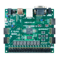
a7%3Areference-manual) Figure 13.1 Accelerometer Interface
The ADXL362 acts as a slave device using an SPI communication scheme. The recommended SPI clock frequency ranges from 1 MHz () to
5 MHz (). The SPI operates in SPI mode 0 with CPOL = 0 and CPHA = 0. All communications with the device must specify a register
address and a flag that indicate whether the communication is a read or a write. Actual data transfer always follows the register address and
communication flag. Device configuration can be performed by writing to the control registers within the accelerometer. Access
accelerometer data by reading the device registers.
For a full list of registers, their functionality, and communication specifications, refer to the ADXL362 datasheet¹.
Several of the built-in functions of the ADXL362 can trigger interrupts that alert the host processor of certain status conditions. Interrupts
can be mapped to either (or both) of two interrupt pins (INT1 (), INT2 ()). Both of these pins require internal FPGA pull-ups when used.
For more details about the interrupts, see the ADXL362 datasheet.
¹ ADXL362 Product Page from Analog Devices (http://www.analog.com/adxl362)
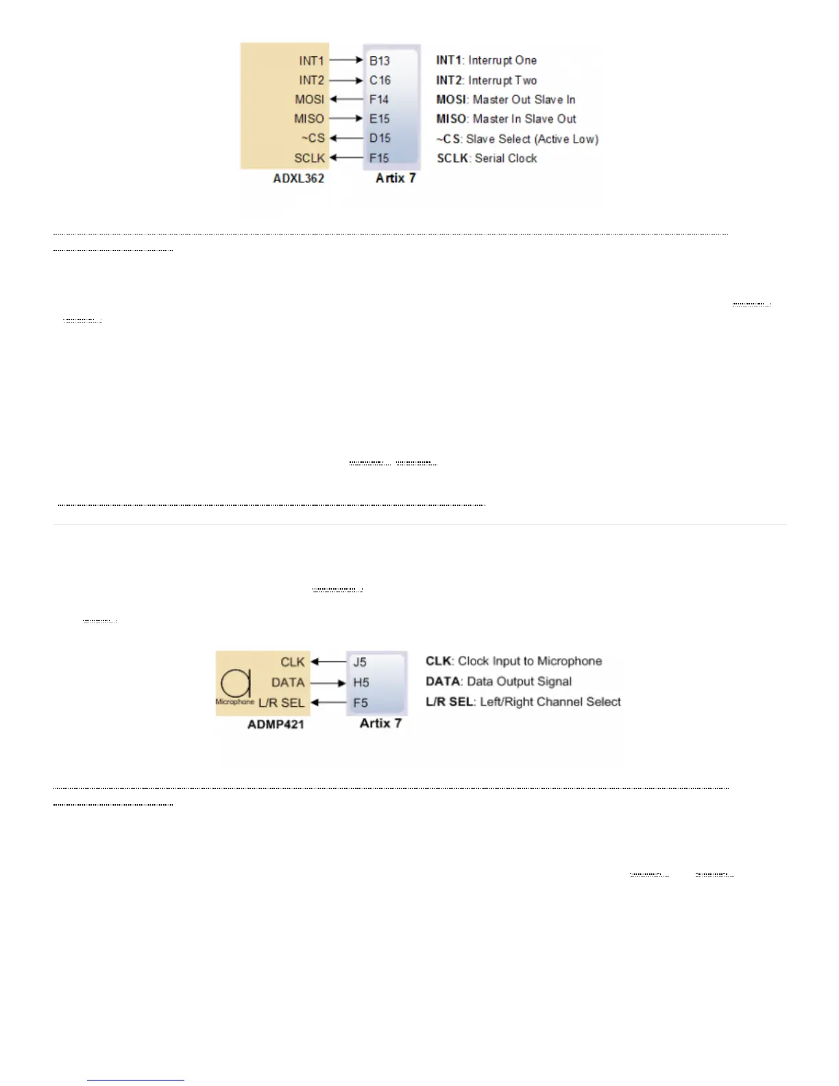
The Nexys A7 board includes an omnidirectional MEMS () microphone. The microphone uses an Analog Device ADMP421 chip which
has a high signal to noise ratio (SNR) of 61dBA and high sensitivity of -26 dBFS. It also has a flat frequency response ranging from 100Hz
to 15 kHz (). The digitized audio is output in the pulse density modulated (PDM) format. The component architecture is shown in Figure
14.1.
(https://reference.digilentinc.com/_detail/reference/programmable-logic/nexys-a7/n4z.png?id=reference%3Aprogrammable-logic%3Anexys-
a7%3Areference-manual) Figure 14.1 Microphone Block Diagram
PDM data connections are becoming more and more popular in portable audio applications, such as cellphones and tablets. With PDM, two
channels can be transmitted with only two wires. The frequency of a PDM signal usually falls in the range of 1 MHz () to 3 MHz (). In a
PDM bitstream, a 1 corresponds to a positive pulse and a 0 corresponds to a negative pulse. A run consisting of all ‘1’s would correspond to
the maximum positive value and a run of ‘0’s would correspond to the minimum amplitude value. Figure 14.1.1 shows how a sine wave is
represented in PDM signal.
13.1 SPI Interface
13.2 Interrupts
14 Microphone
14.1 Pulse Density Modulation (PDM)