https://reference.digilentinc.com/reference/programmable-logic/nexys-a7/reference-manual 26/30
(https://reference.digilentinc.com/_detail/reference/programmable-logic/nexys-a7/n4aa.png?id=reference%3Aprogrammable-logic%3Anexys-
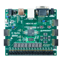
a7%3Areference-manual) Figure 14.1.1 PDM Representation of a Sine Wave
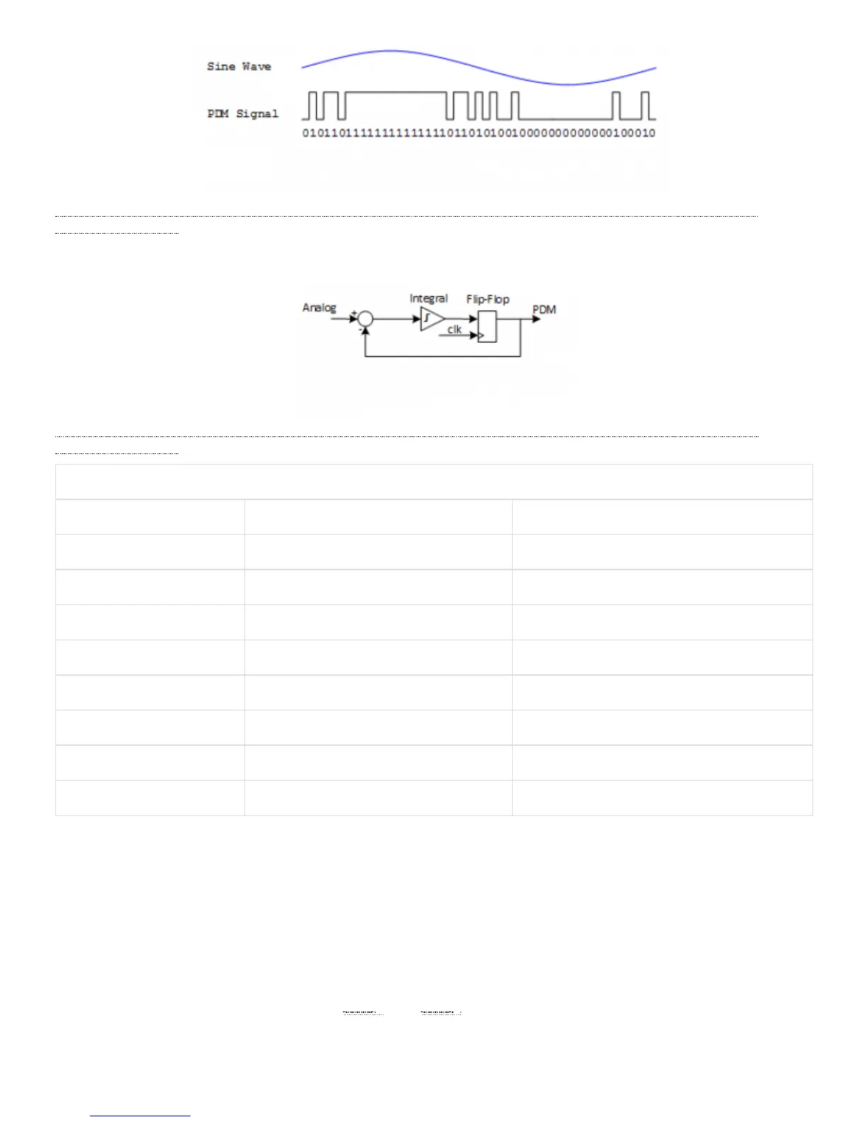
A PDM signal is generated from an analog signal through a process called delta-sigma modulation. A simple idealized circuit of delta-sigma
modulator is shown in Figure 14.1.2.
(https://reference.digilentinc.com/_detail/reference/programmable-logic/nexys-a7/n4ab.png?id=reference%3Aprogrammable-logic%3Anexys-
a7%3Areference-manual) Figure 14.1.2 Simple Delta-Sigma Modulator Circuit
Table 14.1.2. Sigma Delta Modulator with a 0.4Vdd input.
Sum Integrator Out Flip-flop Output
0.4-0=0.4 0+0.4=0.4 0
0.4-0=0.4 0.4+0.4=0.8 1
0.4-1=-0.6 0.8-0.6=0.2 0
0.4-0=0.4 0.2+0.4=0.6 1
0.4-1=-0.6 0.6-0.6=0 0
0.4-0=0.4 0+0.4=0.4 0
0.4-0=0.4 0.4+0.4=0.8 1
0.4-1=-0.6 0.8-0.6=0.2 0
To keep things simple, assume that the analog input and digital output have the same voltage range 0~Vdd. The input of the flip-flop acts
like a comparator (any signal above Vdd/2 is considered as ‘1’ and any input bellow Vdd/2 is considered ‘0’). The input of the integral
circuit is the difference of the input analog signal and the PDM signal of the previous clock cycle. The integral circuit then integrates both of
these inputs, and the output of the integral circuit is sampled by a D-Flip-flop. Table 6 shows the function of the delta-sigma modulator
with an input of 0.4Vdd.
Note that the average of the flip-flop output equals the value of the input analog signal. So in order to get the value of analog input, all that
is needed is a counter that counts the ‘1’s for a certain period of time.
The clock input of the microphone can range from 1 MHz () to 3.3 MHz () based on the sampling rate and data precision requirement of
the applications. The L/R Select signal must be set to a valid level, depending on which edge of the clock the data bit will be read. A low
level on L/RSEL makes data available on the rising edge of the clock, while a high level corresponds to the falling edge of the clock, as
shown in Figure 14.2.1.
14.2 Microphone Digital Interface Timing