https://reference.digilentinc.com/reference/programmable-logic/nexys-a7/reference-manual 14/30
(https://reference.digilentinc.com/_detail/reference/programmable-logic/nexys-a7/n4k.png?id=reference%3Aprogrammable-logic%3Anexys-
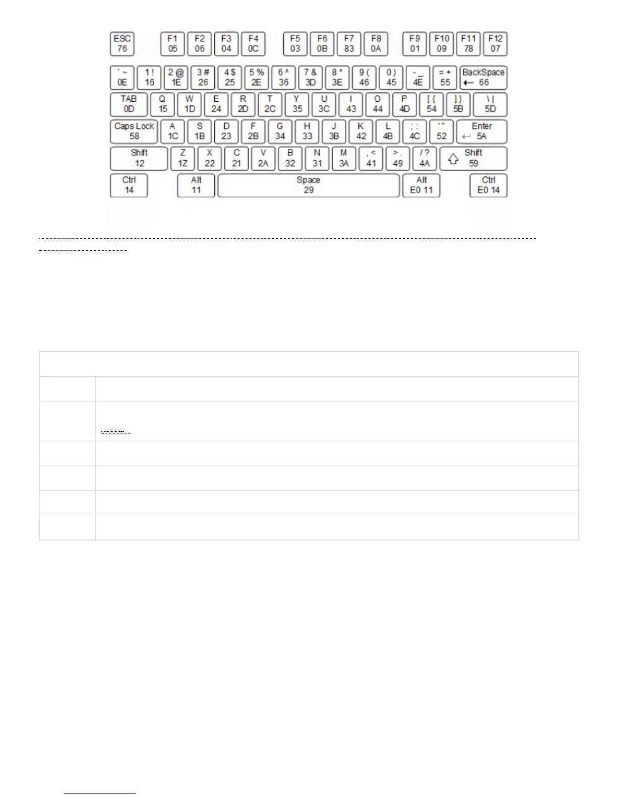
a7%3Areference-manual) Figure 7.2.1 Keyboard Scan Codes
A host device can also send data to the keyboard. Table 7.2.1 shows a list of some common commands a host might send.
The keyboard can send data to the host only when both the data and clock lines are high (or idle). Because the host is the bus master, the
keyboard must check to see whether the host is sending data before driving the bus. To facilitate this, the clock line is used as a “clear to
send” signal. If the host drives the clock line low, the keyboard must not send any data until the clock is released. The keyboard sends data
to the host in 11-bit words that contain a ‘0’ start bit, followed by 8-bits of scan code (LSB first), followed by an odd parity bit, and
terminated with a ‘1’ stop bit. The keyboard generates 11 clock transitions (at 20 to 30 KHz) when the data is sent, and data is valid on the
falling edge of the clock.
Table 7.2.1. Keyboard Commands
Command Action
ED Set Num Lock, Caps Lock, and Scroll Lock LEDs. Keyboard returns FA after receiving ED, then host sends a byte to set
LED () status: bit 0 sets Scroll Lock, bit 1 sets Num Lock, and bit 2 sets Caps lock. Bits 3 to 7 are ignored.
EE Echo (test). Keyboard returns EE after receiving EE
F3 Set scan code repeat rate. Keyboard returns F3 on receiving FA, then host sends second byte to set the repeat rate.
FE Resend. FE directs keyboard to re-send most recent scan code.
FF Reset. Resets the keyboard.
Once entered in stream mode and data reporting is enabled, the mouse outputs a clock and data signal when it is moved; otherwise, these
signals remain at logic ‘1.’ Each time the mouse is moved, three 11-bit words are sent from the mouse to the host device, as shown in Figure
7.3.1. Each of the 11-bit words contains a ‘0’ start bit, followed by 8 bits of data (LSB first), followed by an odd parity bit, and terminated
with a ‘1’ stop bit. Thus, each data transmission contains 33 bits, where bits 0, 11, and 22 are ‘0’ start bits, and bits 11, 21, and 33 are ‘1’ stop
bits. The three 8-bit data fields contain movement data, as shown in Figure 7.3.1. Data is valid at the falling edge of the clock, and the clock
period is 20 to 30 KHz.
The mouse assumes a relative coordinate system wherein moving the mouse to the right generates a positive number in the X field, and
moving to the left generates a negative number. Likewise, moving the mouse up generates a positive number in the Y field, and moving
down represents a negative number (the XS and YS bits in the status byte are the sign bits – a ‘1’ indicates a negative number). The
magnitude of the X and Y numbers represent the rate of mouse movement; the larger the number, the faster the mouse is moving (the XV
and YV bits in the status byte are movement overflow indicators. A ‘1’ means overflow has occurred). If the mouse moves continuously, the
33-bit transmissions are repeated every 50ms or so. The L and R fields in the status byte indicate Left and Right button presses (a ‘1’
indicates the button is being pressed).
7.3 Mouse
 Loading...