https://reference.digilentinc.com/reference/programmable-logic/nexys-a7/reference-manual 19/30
(https://reference.digilentinc.com/_detail/reference/programmable-logic/nexys-a7/n4q.png?id=reference%3Aprogrammable-logic%3Anexys-
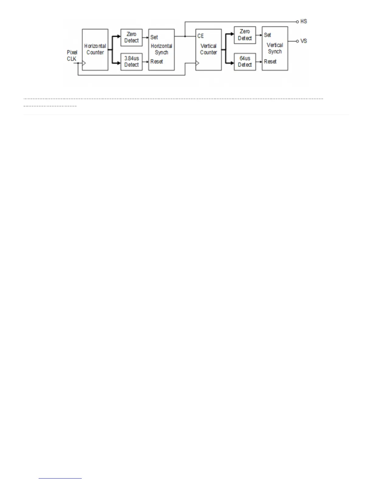
a7%3Areference-manual) Figure 8.1.4 VGA Display Controller Block Diagram
The Nexys A7 board includes two tri-color LEDs, sixteen slide switches, six push buttons, sixteen individual LEDs, and an eight-digit
seven-segment display, as shown in Figure 9.1. The pushbuttons and slide switches are connected to the FPGA via series resistors to
prevent damage from inadvertent short circuits (a short circuit could occur if an FPGA pin assigned to a pushbutton or slide switch was
inadvertently defined as an output). The five pushbuttons arranged in a plus-sign configuration are “momentary” switches that normally
generate a low output when they are at rest, and a high output only when they are pressed. The red pushbutton labeled “CPU RESET,” on
the other hand, generates a high output when at rest and a low output when pressed. The CPU RESET button is intended to be used in
EDK designs to reset the processor, but you can also use it as a general purpose pushbutton. Slide switches generate constant high or low
inputs depending on their position.
9 Basic I/O