https://reference.digilentinc.com/reference/programmable-logic/nexys-a7/reference-manual 7/30
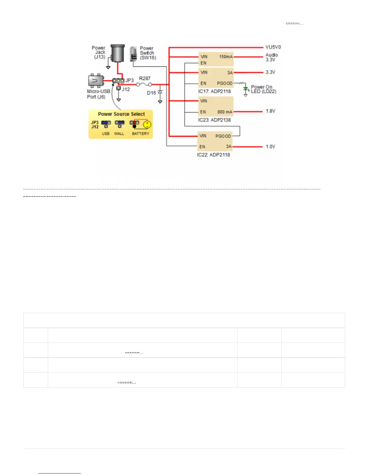
All Nexys A7 power supplies can be turned on and off by a single logic-level power switch (SW16). A power-good LED () (LD22), driven
by the “power good” output of the ADP2118 supply, indicates that the supplies are turned on and operating normally. An overview of the
Nexys A7 power circuit is shown in Figure 1.1.
(https://reference.digilentinc.com/_detail/reference/programmable-logic/nexys-a7/n4d.png?id=reference%3Aprogrammable-logic%3Anexys-
a7%3Areference-manual) Figure 1.1 Nexys A7 Power Circuit
The USB port can deliver enough power for the vast majority of designs. Our out-of-box demo draws ~400mA of current from the 5V
input rail. A few demanding applications, including any that drive multiple peripheral boards, might require more power than the USB port
can provide. Also, some applications may need to run without being connected to a PC’s USB port. In these instances, an external power
supply or battery pack can be used.
An external power supply can be used by plugging into to the power jack (JP3) and setting jumper J13 to “wall”. The supply must use a
coax, center-positive 2.1mm internal-diameter plug, and deliver 4.5VDC to 5.5VDC and at least 1A of current (i.e., at least 5W of power).
Many suitable supplies can be purchased from Digilent, through Digi-Key, or other catalog vendors.
An external battery pack can be used by connecting the battery’s positive terminal to the center pin of JP3 and the negative terminal to the
pin labeled J12, directly below JP3. Since the main regulator on the Nexys A7 cannot accommodate input voltages over 5.5VDC, an external
battery pack must be limited to 5.5VDC. The minimum voltage of the battery pack depends on the application: if the USB Host function
(J5) is used, at least 4.6V needs to be provided. In other cases, the minimum voltage is 3.6V.
Voltage regulator circuits from Analog Devices create the required 3.3V, 1.8V, and 1.0V supplies from the main power input. Table 1.1
provides additional information. Typical currents depend strongly on FPGA configuration and the values provided are typical of medium
size/speed designs.
Table 1.1 Nexys A7 power supplies.
Supply Circuits Device Current (max/typical)
3.3V FPGA I/O, USB ports, Clocks, RAM () I/O, Ethernet, SD slot, Sensors, Flash IC17: ADP2118 3A/0.1 to 1.5A
1.0V FPGA Core IC22: ADP2118 3A/ 0.2 to 1.3A
1.8V DDR2, FPGA Auxiliary and RAM () IC23: ADP2118 0.8A/ 0.5A
The Nexys A7 features overcurrent and overvoltage protection on the input power rail. A 3.5A fuse (R287) and a 5V Zener diode (D16)
provide a non-resettable protection for other on-board integrated circuits, as displayed in Figure 2. Applying power outside of the specs
outlined in this document is not covered by warranty. If this happens, either or both might get permanently damaged. The damaged parts
are not user-replaceable.
1.1 Protection