Brine side
Collector
Caution
The length of the collector hose varies depend-
ing on the rock/soil conditions, climate zone
and on the climate system (radiators or under-
floor heating) and the heating requirement of
the building Each installation must be sized
individually.
Max length per coil for the collector should not exceed
400 m.
In those cases where it is necessary to have several col-
lectors, these should be connected in parallel with the
possibility for adjusting the flow of the relevant coil.
For surface soil heat, the hose should be buried at a
depth determined by local conditions and the distance
between the hoses should be at least 1 metre.
For several bore holes, the distance between the holes
must be determined according to local conditions.
Ensure the collector hose rises constantly towards the
heat pump to avoid air pockets. If this is not possible,
airvents should be used.
Because the temperature of the brine system can fall
below 0 °C, it must be protected against freezing down
to -15 °C. When making the volume calculation, use 1
litres of ready mixed brine per metre of collector hose
(applies when using PEM-hose 40x2.4 PN 6.3) as a guide
value.
Anti freeze must be mixed according to manufacturer's
instructions to ensure frost protection and should be
checked using a refractometer.
NOTE
Ensure that cleaning agent has been removed
from the entire system before the anti-freeze
is added.
NIBE Energy Systems Limited recommends water treat-
ments (supplied by e.g. Fernox and Sentinel) specifically
designed for heat pumps.
Side connection
It is possible to angle the brine connections, for connec-
tion to the side instead of top connection.
To angle out a connection:
1.
Disconnect the pipe at the top connection.
2.
Angle the pipe in the desired direction.
3.
If necessary, cut the pipe to the desired length.
Connecting the brine side
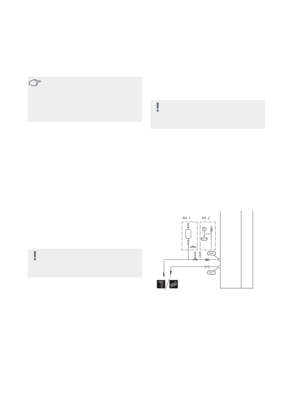
■
Insulate all indoor brine pipes against condensation.
■
The level vessel must be installed at the highest point
in the brine system, on the incoming pipe before the
brine pump (Alt. 1).
If the level vessel cannot be placed at the highest point,
an expansion vessel must be used (Alt. 2).
NOTE
Note that condensation may drip from the level
vessel. Position the vessel so that this does not
harm other equipment.
■
Details of the antifreeze used must be shown on the
level vessel.
■
Install the enclosed safety valve under the level vessel
as illustrated. The entire length of the overflow water
pipe from the safety valve must be inclined to prevent
water pockets and must also be frost-free.
■
Install shut off valves as close to the heat pump as
possible.
■
Fit the enclosed filterball on the incoming pipe.
In the case of connection to an open groundwater sys-
tem, an intermediate frost-protected circuit must be
provided, because of the risk of dirt and freezing in the
evaporator. This requires an extra heat exchanger.
Heating medium side
Connecting the climate system
A climate system is a system that regulates indoor com-
fort with the help of the control system in F1155 and for
example radiators, underfloor heating/cooling, fan
convectors etc.
■
Install all necessary safety devices, shut-off valves (as
close to the heat pump as possible) and the enclosed
filterball.
■
The safety valve must have a maximum 0.25 MPa (2.5
bar) opening pressure and be installed on the heating
medium return as illustrated. The entire length of the
overflow water pipe from the safety valves must be
inclined to prevent water pockets and must also be
frost proof.
NIBE F1155Chapter 4 | Pipe connections16
 Loading...


