■
When connecting to a system with thermostats on all
radiators, a relief valve must be fitted, or some of the
thermostats must be removed to ensure sufficient flow.
Before installing the heat pump in an existing system, it
is important that the system is properly flushed through.
Even if the heat pump is to be installed in a new system,
the heat pump and system should be flushed.
NOTE
Ensure that cleaning agent has been removed
from the entire system before adding inhibitor.
After flushing an inhibitor should be used for long-term
anti-corrosion protection.
NIBE Energy Systems Limited recommends water treat-
ments (supplied by e.g. Fernox and Sentinel) specifically
designed for heat pumps.
Water heater
Connecting the hot water heater
NOTE
If F1155 is not docked to a water heater or if it
is to work with fixed condensing, the connec-
tion for the water heater (XL9) must be
plugged.
■
Any docked hot water heater must be fitted with ne-
cessary set of valves.
■
The mixing valve must be installed if the setting is
changed so that the temperature can exceed 60 °C.
■
The setting for hot water is made in menu 5.1.1.
■
The safety valve must have a maximum opening pres-
sure of 1.0 MPa (10.0 bar) and be installed on the in-
coming domestic water line as illustrated. The entire
length of the overflow water pipe from the safety valve
must be inclined to prevent water pockets and must
also be frost-free.
Caution
Hot water production is activated in menu 5.2
or in the start guide.
Fixed condensing
If F1155 is to work towards the water heater with fixed
condensing you must connect an external flow sensor
(BT25) according to the description on page 24. In addi-
tion, you must perform the following menu settings.
Menu setting (local vari-
ations may be required)
Menu
Desired temperature in the
tank.
1.9.3.1 - min. flow line temp.
heating
Desired temperature in the
tank.
5.1.2 - max flow line temper-
ature
intermittent5.1.10 - op. mod heat med
pump
manual4.2 - op. mode
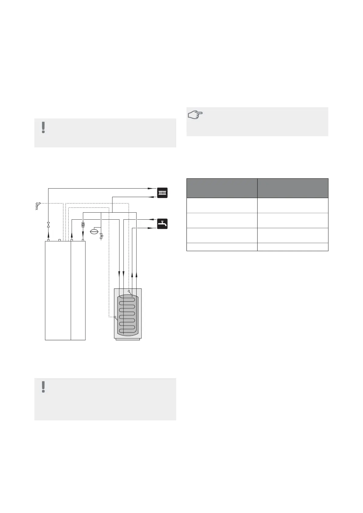
Docking alternatives
F1155 can be connected in several different ways, some
of which are shown below.
Further option information is available at
www.nibe.co.uk and in the respective assembly instruc-
tion for the accessory used. See page 61 for a list of ac-
cessories that can be used with F1155.
17Chapter 4 | Pipe connectionsNIBE F1155

 Loading...


