Optional connections
Uplink
Connect the network connected cable (straight, Cat.5e
UTP) with RJ45-contact (male) to RJ45 contact (female)
on the rear of the heat pump.
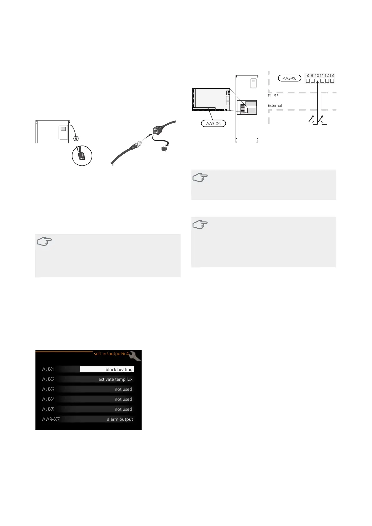
External connection options
F1155 has software-controlled AUX inputs/outputs on
the input board (AA3), for connecting the external switch
function or sensor. This means that, when an external
switch function or sensor is connected to one of six spe-
cial connections, the correct function must be selected
for the correct connection in the software in F1155.
Caution
If an external switch function or sensor is con-
nected to F1155, the function to use input or
output must be selected in menu 5.4, see page
51.
Selectable inputs on the input board for these functions
are:
AA3-X6:9-10AUX1
AA3-X6:11-12AUX2
AA3-X6:13-14AUX3
AA3-X6:15-16AUX4
AA3-X6:17-18AUX5
Selectable output is AA3-X7.
block heating
activate temp lux
not used
not used
not used
alarm output
soft in/outputs5.4
The example above uses the inputs AUX1 (X6:9-10) andAUX2
(X6:11-12) on the input circuit board (AA3).
Caution
Some of the following functions can also be
activated and scheduled via menu settings.
Possible selection for AUX inputs
Caution
The external switch function or sensor is con-
nected to terminal block X6 on the input board
(AA3), which is positioned behind the front
cover. The function for use input must be selec-
ted in menu 5.4.
Temperature sensor, hot water top
A temperature sensor for hot water top can be connec-
ted to F1155 for showing the water temperature at the
top of the tank.
The temperature sensor, hot water top (BT7) is connected
to the selected input (menu 5.4, see page 51) on terminal
block X6 on the input card (AA3) which is located behind
the front cover and in a submerged tube on the water
heater.
Use a 2 core cable of at least 0.5 mm2 cable area.
Temperature sensor, cooling/heating
An extra temperature sensor (BT74) can be connected
to F1155 in order to determine when it is time to switch
between heating and cooling operation.
The temperature sensor is connected to the selected in-
put (menu 5.4, the alternative is only displayed if cooling
accessory is installed, se page 51) on terminal block X6
on the input card (AA3) which is located behind the front
cover and is positioned in a suitable place in the climate
system.
Use a 2 core cable of at least 0.5 mm² cable area.
Switch for external blocking of addition and/or
compressor
Blocking for addition heat and compressor is connected
on two different AUX inputs.
If external blocking of additional heat and/or compressor
is wanted, this can be connected to terminal block X6
on the input board (AA3), which is positioned behind
the front cover.
NIBE F1155Chapter 5 | Electrical connections26
 Loading...


